
Continuous Commutation Failure Suppression Method and Device Based on Adaptive Firing Angle Compensation

A technology of commutation failure and trigger angle, which is applied in the direction of circuit devices, emergency treatment AC circuit layout, power transmission AC network, etc., can solve problems such as DC blocking, cascading failures, continuous commutation failures, etc., to increase the commutation margin The effect of suppressing continuous commutation failure and reducing the probability of continuous commutation failure

Active Publication Date: 2021-11-02
HUAZHONG UNIV OF SCI & TECH +1
View PDF0 Cites 0 Cited by
  • Summary
  • Abstract
  • Description
  • Claims
  • Application Information

AI Technical Summary

Problems solved by technology

[0004] In view of the defects of the prior art, the purpose of the present invention is to provide a continuous commutation failure suppression method and device based on adaptive firing angle compensation, aiming at solving the problem of continuous commutation easily caused if the fault is not cleared in time after the occurrence of an AC fault Failure, even technical problems causing DC blocking and cascading failures

Method used


Image

  • Continuous Commutation Failure Suppression Method and Device Based on Adaptive Firing Angle Compensation
  • Continuous Commutation Failure Suppression Method and Device Based on Adaptive Firing Angle Compensation
  • Continuous Commutation Failure Suppression Method and Device Based on Adaptive Firing Angle Compensation

Examples


Embodiment Construction

[0056]In order to make the object, technical solution and advantages of the present invention clearer, the present invention will be further described in detail below in conjunction with the accompanying drawings and embodiments. It should be understood that the specific embodiments described here are only used to explain the present invention, not to limit the present invention. In addition, the technical features involved in the various embodiments of the present invention described below can be combined with each other as long as they do not constitute a conflict with each other.

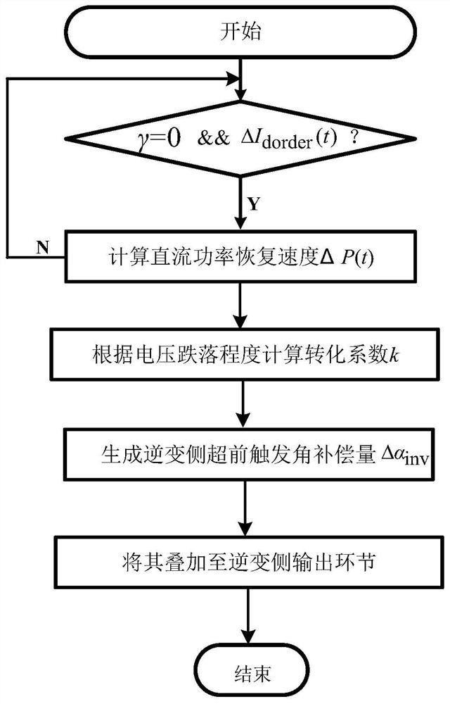
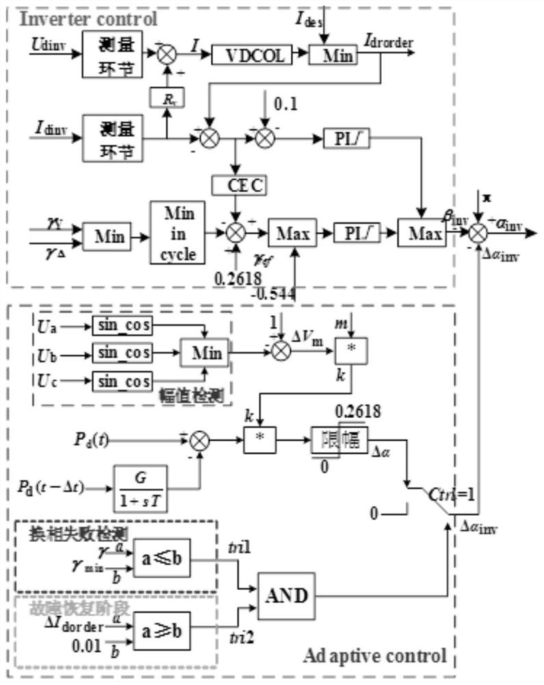
[0057] The invention provides a continuous commutation failure suppression method based on adaptive trigger compensation, the purpose of which is to judge whether the controller is put into operation by detecting whether the first commutation failure occurs and whether it is in the rising stage of DC current recovery; DC power recovery speed and AC voltage drop degree, from which the trigger lead...


PUM


Abstract

The invention discloses a continuous commutation failure suppression method and device based on adaptive trigger angle compensation, which includes detecting whether a commutation failure occurs in a DC power transmission system, and if a commutation failure occurs, according to the change amount of the DC current command value on the inverter side Size, to determine whether it is in the rising stage of DC current recovery, if so, collect the DC power value in real time, and calculate the DC power recovery speed during the recovery process of the DC system; dynamically adjust the trigger angle conversion according to the drop degree of the commutation bus voltage amplitude on the inverter side coefficient; the DC power recovery speed is multiplied by the conversion coefficient, and after the clipping link, the compensation amount for triggering the lead angle of the inverter side is generated; superimposed to the output link of the inverter side controller. The continuous commutation failure suppression method provided by the present invention can take into account the DC power recovery speed and the degree of AC voltage drop, and perform self-adaptive and dynamic adjustment to the trigger angle of the inverter side without adding additional devices and equipment, with low investment and easy implementation.

Description

technical field [0001] The present invention relates to the field of electrical engineering, in particular to a continuous commutation failure suppression method and device based on adaptive firing angle compensation. Background technique [0002] The application of commutation converter high-voltage direct current (LCC-HVDC) technology in the traditional power grid realizes long-distance power transmission and solves the uneven distribution of energy load in my country; When the terminal AC system fails, it is easy to cause continuous commutation failure and even DC blocking, causing cascading failures and deteriorating the stable operation of the power system. [0003] Therefore, it is necessary to conduct in-depth research on how to suppress the occurrence of continuous commutation failures to prevent DC blocking and avoid serious impacts on the safe and stable operation of the AC-DC hybrid power grid. Studies have shown that if the fault is not cleared in time after the ...

Claims


Application Information

Patent Timeline
Patent Type & Authority Patents(China)
IPC IPC(8): H02J3/00H02J3/36
CPCH02J3/36H02J3/001Y02E60/60
Inventor 姚伟杨程祥李培平高东学李程昊张景超文劲宇
Owner HUAZHONG UNIV OF SCI & TECH
Learn More