Laminating assembly, laminating pad and laminating equipment
A technology for bonding pads and components, which is applied in the direction of instruments, identification devices, etc., can solve the problems of poor bonding quality between curved cover plates and flexible screens, low product yield, and easy generation of air bubbles, etc., to achieve better bonding quality, Product yield is high and the effect of reducing air bubbles
- Summary
- Abstract
- Description
- Claims
- Application Information
AI Technical Summary
Problems solved by technology
Method used
Image
Examples
Embodiment approach
[0125] In one embodiment, the first slider and the second slider jointly support the fitting pad, and the relative movement between the first slider and the second slider is an active movement.
[0126] In another embodiment, the fitting assembly further includes a support block located between the first slider and the second slider. The first sliding block, the supporting block and the second sliding block jointly support the bonding pad, the supporting block does not move in the second direction, and the movement of the first sliding block and the second sliding block relative to the supporting block is an active movement.
[0127] In yet another embodiment, the fitting assembly further includes a pressing block located between the first slider and the second slider. The first sliding block, the extruding block and the second sliding block jointly support the fitting pad. When the extruding block squeezes into the space between the first sliding block and the second sliding ...
other Embodiment approach
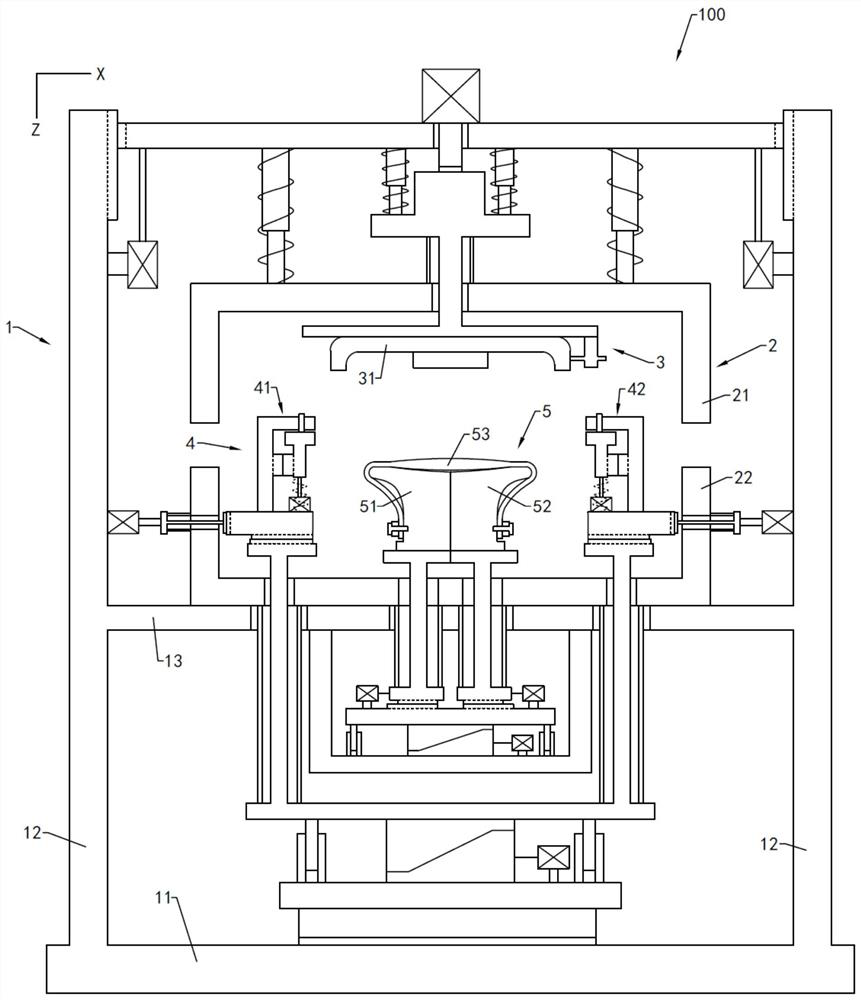
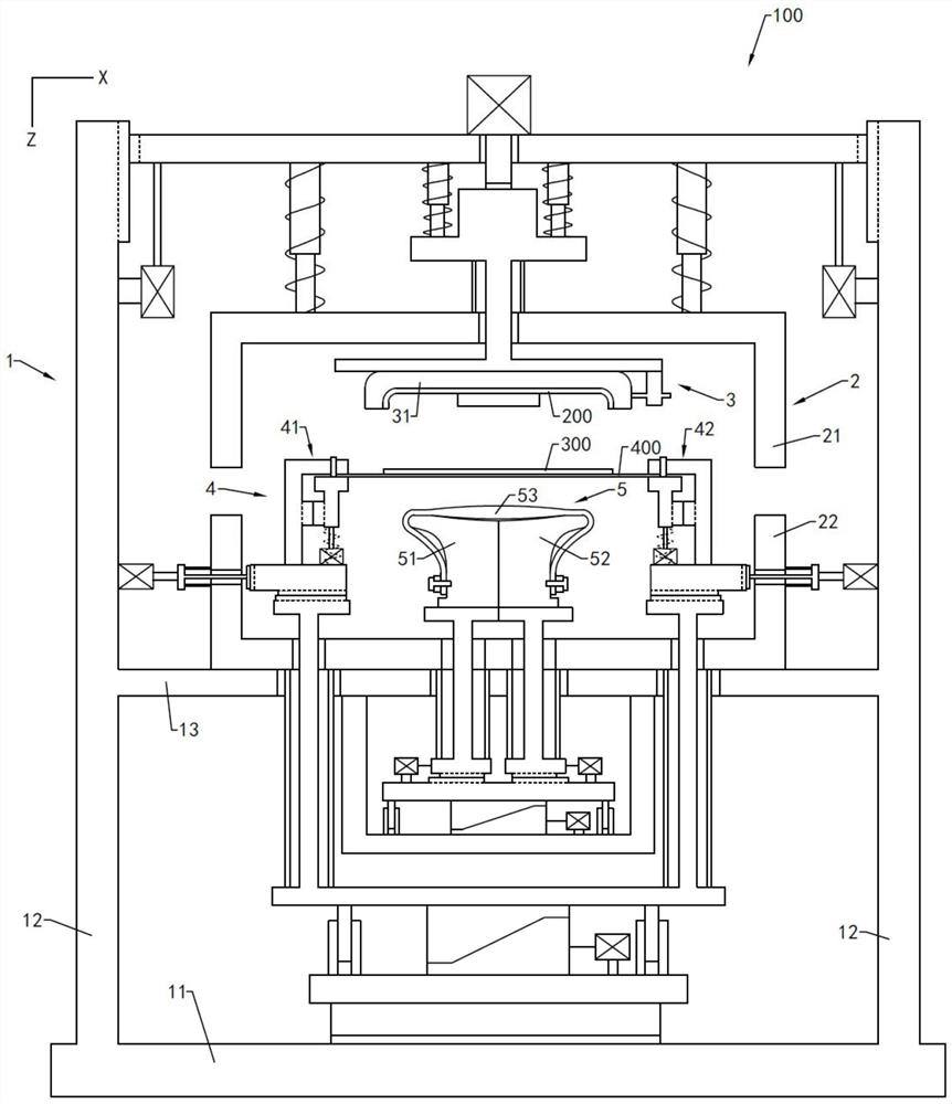
[0412] In other embodiments, if the first clamping claw 41 and the second clamping claw 42 have no degree of freedom in the first direction Z, the first clamping claw 41 and the second clamping claw 42 are positioned through a mechanical structure so that both Or achieve height consistency in the first direction Z between steps 001. If the first clamping claw 41 and the second clamping have no degree of freedom in the second direction X, the first clamping claw 41 and the second clamping claw 42 are The distance from the bonding pad 53 in the second direction X is equal.
[0413] In this embodiment, the bonding method moves the core components in the bonding device 100 to a suitable position first through the equipment alignment step, so as to facilitate the smooth progress of the subsequent steps, reduce the debugging time of the subsequent steps, and also facilitate The lamination accuracy of the curved cover 200 and the flexible screen 300 is increased.
[0414] It can be...
other Embodiment approach
[0439] In other embodiments, when the bonding method is used to bond the curved cover 200 and the flexible screen 300 with a small bending angle in the edge area, the two ends of the carrier film 400 may not be limited to move to the first side 513 and the second side. In the concave region formed by the side surface 523 , the flexibility of the positions of both ends of the carrying film 400 is higher. Similarly, the first side 513 and the second side 523 may not be concavely designed, but planar.
PUM
| Property | Measurement | Unit |
|---|---|---|
| Bending angle | aaaaa | aaaaa |
| Bending angle | aaaaa | aaaaa |
| Bending angle | aaaaa | aaaaa |
Abstract
Description
Claims
Application Information
 - R&D
- Intellectual Property
- Life Sciences
- Materials
- Tech Scout
- Unparalleled Data Quality
- Higher Quality Content
- 60% Fewer Hallucinations
Browse by: Latest US Patents, China's latest patents, Technical Efficacy Thesaurus, Application Domain, Technology Topic, Popular Technical Reports.
© 2025 PatSnap. All rights reserved.Legal|Privacy policy|Modern Slavery Act Transparency Statement|Sitemap|About US| Contact US: help@patsnap.com


