Flow distribution design method and device for micro evaporation tube type combustion chamber

A flow distribution and combustion chamber technology, applied in computer-aided design, calculation, special data processing applications, etc., can solve the problems of long calculation time and high simulation cost, and achieve the effect of alleviating the long calculation time

Active Publication Date: 2020-10-30
CIVIL AVIATION UNIV OF CHINA
View PDF6 Cites 1 Cited by
  • Summary
  • Abstract
  • Description
  • Claims
  • Application Information

AI Technical Summary

Problems solved by technology

[0010] In view of this, the object of the present invention is to provide a flow distribution design method and device for a miniature evaporator tube combus

Method used


Image

  • Flow distribution design method and device for micro evaporation tube type combustion chamber
  • Flow distribution design method and device for micro evaporation tube type combustion chamber
  • Flow distribution design method and device for micro evaporation tube type combustion chamber

Examples


Embodiment 1

[0058] Embodiment 1 of the present invention provides a flow distribution design method for a miniature evaporator tube combustor, including:

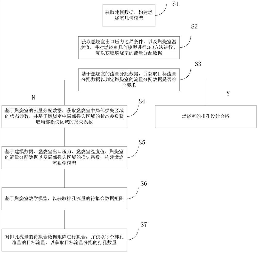
[0059] S1: Obtain modeling data and build a geometric model of the combustion chamber;

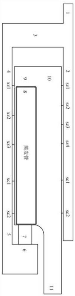
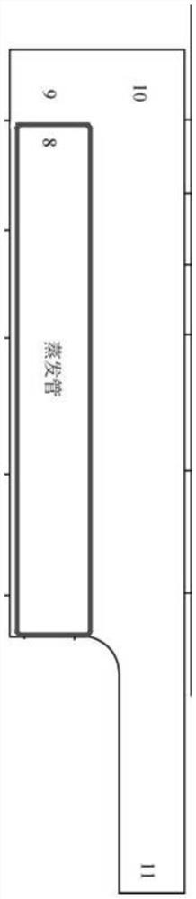
[0060] Further, the modeling data includes the width of the combustion chamber inlet, the height of the ring, the width of the head, the length of the upper and lower rings, the inner and outer diameters of the evaporation tube, the length of the evaporation tube, the size of the flame tube and the height of the outlet of the combustion chamber;

[0061] S2: Obtain the outlet pressure boundary conditions of the combustor and the temperature value of the combustor, and perform CFD calculation on the geometric model of the combustor to obtain the flow distribution data of the combustor, which includes the flow distribution data of each row Orifice flow and evaporation tube flow;

[0062] S3: Obtain target flow distribution data based on the flow dis...

Embodiment 2

[0138] Embodiment 2 of the present invention provides a flow distribution design device for a miniature evaporator tube combustor, including:

[0139] Data acquisition module: used to acquire modeling data and build a combustion chamber geometric model;

[0140] Calculation module: used to obtain the combustion chamber outlet pressure boundary condition and the combustion chamber temperature value, and perform CFD calculation on the combustion chamber geometric model to obtain the flow distribution data of the combustion chamber, the flow distribution data of the combustion chamber includes The flow rate of each row hole and the flow rate of the evaporation tube;

[0141] Judgment module: used to obtain target flow distribution data based on the flow distribution data of the combustion chamber to determine whether the flow distribution data of the combustion chamber meets the requirements;

[0142] If not, then execute the step of S4;

[0143] If so, the design of the exhaus...


PUM


Abstract

The embodiment of the invention provides a flow distribution design method and device for a micro evaporation tube type combustion chamber, and relates to the technical field of combustion chamber designs. The method comprises: obtaining modeling data, and constructing a combustion chamber geometric model; calculating the combustion chamber geometric model through a CFD method to obtain flow distribution data of the combustion chamber, and obtaining target flow distribution data based on the flow distribution data of the combustion chamber to judge whether the flow distribution data of the combustion chamber meets requirements or not; if not, executing flow distribution data based on the combustion chamber, obtaining state parameters of a local loss area in the combustion chamber, and obtaining a loss coefficient of the local loss area based on the state parameters of the local loss area in the combustion chamber; and constructing a combustion chamber mathematical model, obtaining andfitting a to-be-fitted data matrix of the discharge hole flow, and obtaining the punching number distributed by the target flow. The technical problems of long calculation time and high simulation cost of a perforation flow rule method in the prior art can be solved.

Description

technical field [0001] The invention relates to the technical field of combustion chamber design, in particular to a flow distribution design method and device for a miniature evaporation tube type combustion chamber. Background technique [0002] According to whether the design needs flow empirical parameters, the current flow distribution design methods of combustors can be roughly divided into two categories. [0003] Flow empirical parameter method is required: use fluid mechanics formula to analyze and calculate the combustion chamber, one-dimensional network method. [0004] A method that does not require empirical parameters of the flow: the parametric CFD method. [0005] The analysis and calculation method is a common method for traditional combustion chamber design. It can quickly obtain the design scheme corresponding to the target flow distribution, but the accuracy cannot be guaranteed. It is usually used to obtain the initial scheme, and generally needs to be ...

Claims


Application Information

Patent Timeline
IPC IPC(8): G06F30/13G06F119/08G06F119/14
CPCG06F30/13G06F2119/08G06F2119/14
Inventor 于军力李奥特王伟
Owner CIVIL AVIATION UNIV OF CHINA
Why Eureka
Try Eureka