
Constant velocity spinning take-up roll fixing device based on circular linear velocity law

A technology of fixing device and take-up roller, applied in the field of textile and spinning, can solve the problems of complicated operation, yarn breakage, difficulty in fixing, etc.

Inactive Publication Date: 2020-10-30
湖州益浩毛纺原料有限公司
View PDF8 Cites 0 Cited by
  • Summary
  • Abstract
  • Description
  • Claims
  • Application Information

AI Technical Summary

Problems solved by technology

[0003] In the twisting process, it is necessary to take up the finished yarn. Usually, the take-up roller is fixed on the take-up rotating block through a special fixture to rotate and take up the line. However, due to the wide variety of existing take-up rollers, it is often The diameters of the wire rolls are different, which leads to the need to prepare special fixtures of different specifications when fixing the take-up rolls, which leads to an increase in equipment costs, and the existing ones are usually fixed by bolts, which is complicated to operate, difficult to fix, and low in work efficiency. The take-up roller is often rigidly connected directly to the take-up motor, which leads to the fixed speed of the take-up roller and the motor, resulting in fluctuations in the motor speed when the voltage is unstable, which drives the speed of the take-up roller to fluctuate, thereby affecting the take-up effect, and Sudden increase in speed can also easily cause yarn breakage, resulting in a decline in product quality

Method used


Image

  • Constant velocity spinning take-up roll fixing device based on circular linear velocity law
  • Constant velocity spinning take-up roll fixing device based on circular linear velocity law
  • Constant velocity spinning take-up roll fixing device based on circular linear velocity law

Examples


Embodiment Construction

[0025] The following will clearly and completely describe the technical solutions in the embodiments of the present invention with reference to the accompanying drawings in the embodiments of the present invention. Obviously, the described embodiments are only some, not all, embodiments of the present invention. Based on the embodiments of the present invention, all other embodiments obtained by persons of ordinary skill in the art without making creative efforts belong to the protection scope of the present invention.

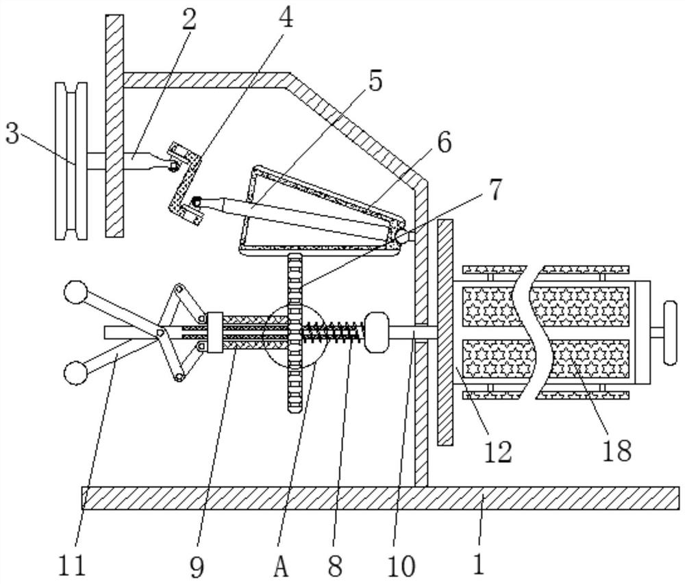
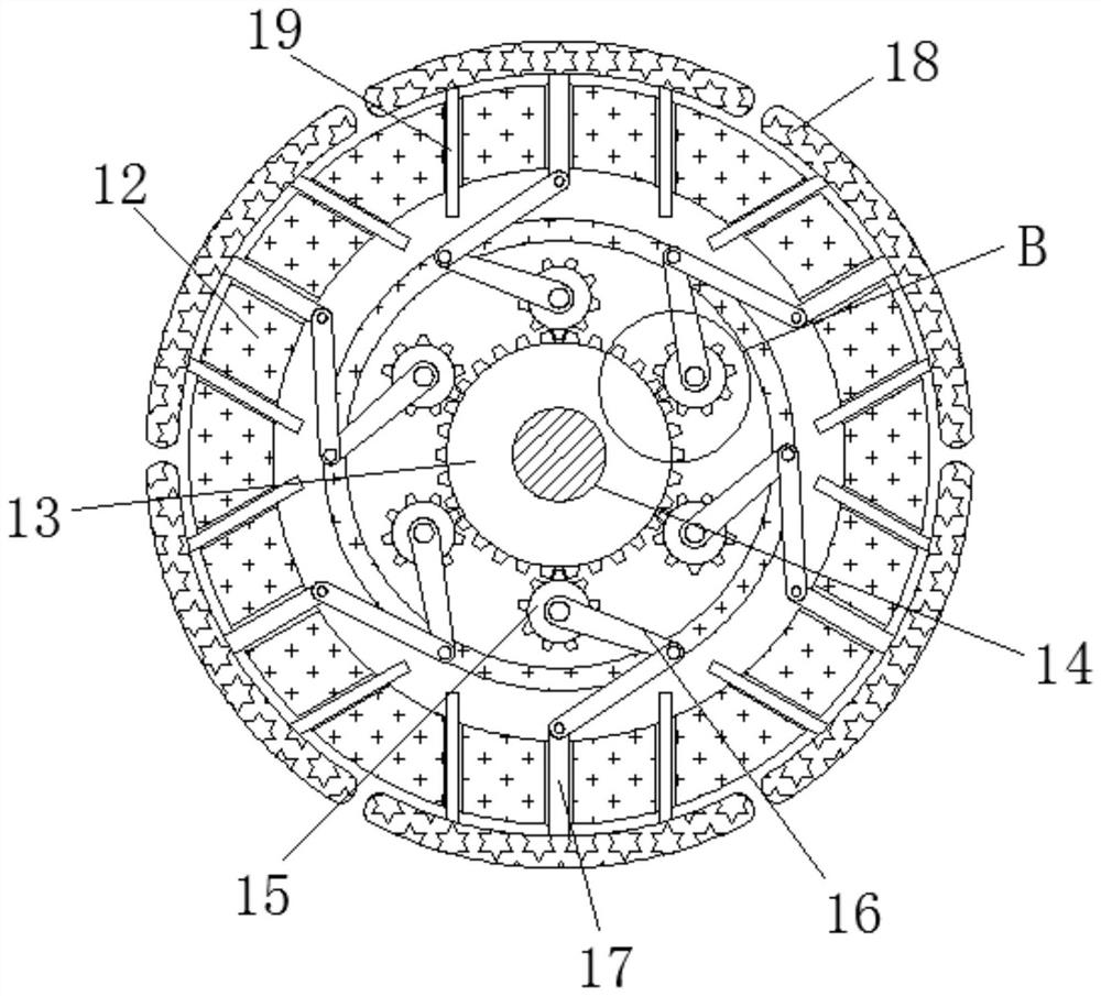
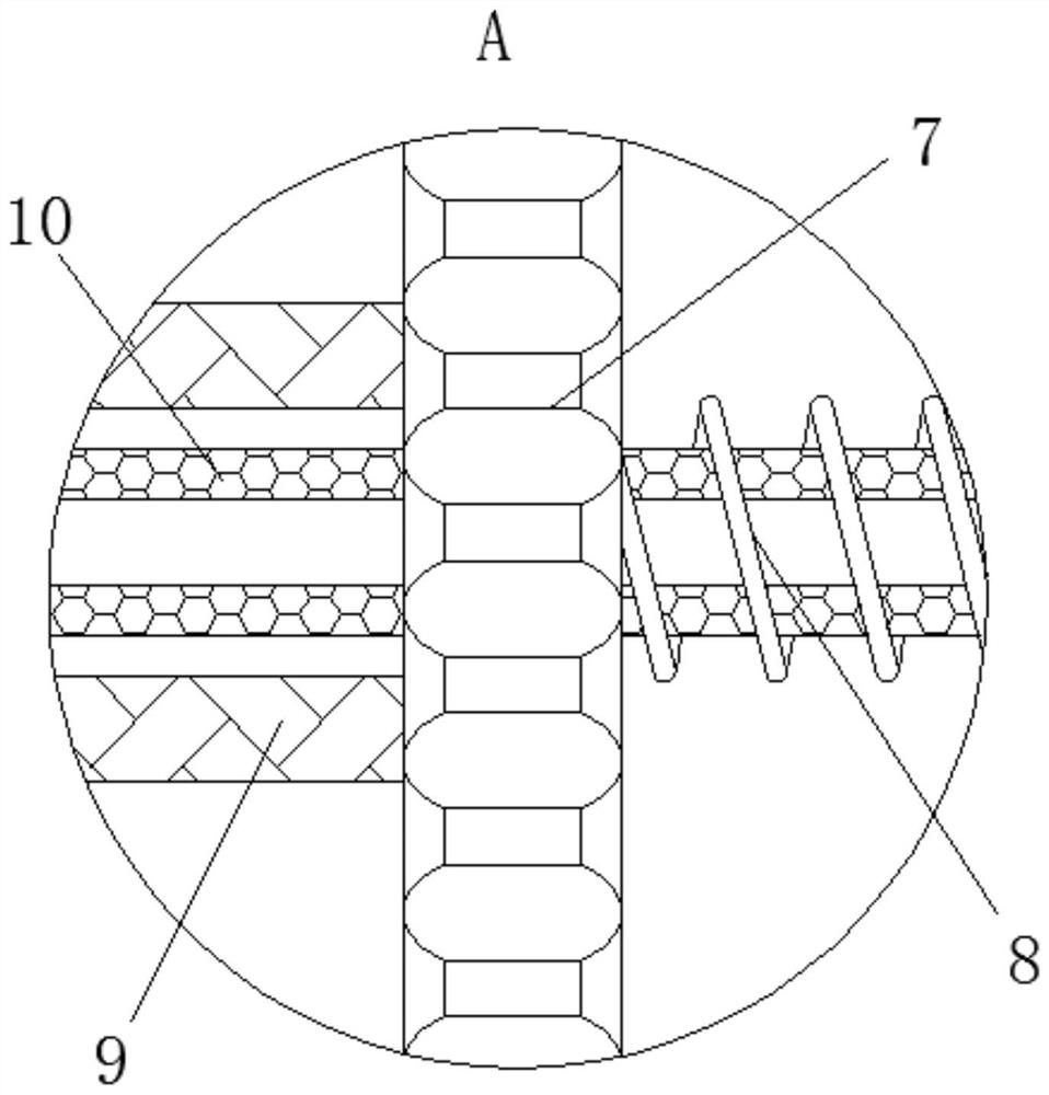
[0026] see Figure 1-4 , a fixed-speed spinning take-up roller fixing device based on the circular line speed law, including a support frame 1, a main shaft 2, a transmission wheel 3, a steering block 4, an inclined shaft 5, a flywheel 6, a movable gear 7, and a spring 8 , slider 9, take-up shaft 10, speed regulating lever 11, positioning block 12, fixed gear 13, fixed rod 14, connecting gear 15, connecting rod 16, push rod 17, fixed plate 18, guide rod 19.

...


PUM


Abstract

The invention relates to the technical field of spinning and yarn manufacturing and discloses a constant velocity spinning take-up roll fixing device based on a circular linear velocity law. The constant velocity spinning take-up roll fixing device comprises a supporting rack, wherein a spindle is movably connected in the supporting rack; a transmission wheel is fixedly connected outside the spindle; a turning block is hinged outside the spindle; an oblique shaft is hinged outside the turning block; a velocity regulating wheel is fixedly connected outside the oblique shaft; a movable gear is in engaged connection outside the velocity regulating wheel; a spring is fixedly connected outside of the movable gear; and a slide block is fixedly connected outside the movable gear. By matching thespindle, the transmission wheel, the turning block, the oblique shaft, the velocity regulating wheel, the movable gear, the spring, the slide block, a take-up roll and a velocity regulating rod in use, an effect of regulating the rotating velocity of a take-up shaft automatically is achieved, and the stability of the rotating velocity of a positioning block is guaranteed effectively, so that a take-up effect is guaranteed. A condition that a yarn which is too high in rotating velocity is broken is avoided effectively, so that the quality of a product is guaranteed and the economical waste is reduced.

Description

technical field [0001] The invention relates to the technical field of textile spinning, in particular to a fixed-speed spinning take-up roller fixing device based on the law of circular linear velocity. Background technique [0002] A loom twists many plant and animal fibers together to form threads or yarns, which can be used to weave cloth. The earliest spinning machine has a very simple structure and was first used in the 14th century. After the 18th century, people invented better spinning machines, which made the textile industry the number one industry. All of spinning machine the most only does two pieces thing: first substantial amounts of chopped fiber is aggregated into loose cotton thread, then a little release of cotton thread, is twined into fine and closely woven cotton thread, and cotton thread is the most elongated through afterturn. [0003] In the twisting process, it is necessary to take up the finished yarn. Usually, the take-up roller is fixed on the ...

Claims


Application Information

Patent Timeline
IPC IPC(8): B65H54/42B65H54/54
CPCB65H54/42B65H54/543B65H2701/31
Inventor 刘中恺
Owner 湖州益浩毛纺原料有限公司
Learn More