Material transfer device for highway construction

A technology for engineering construction and transfer devices, which is applied in the directions of transportation and packaging, conveyor objects, chemical instruments and methods, etc., can solve the problems of inability to screen coarse aggregates, and achieve the goal of intensifying collisions, increasing the amount of grabbing, and enhancing the screening effect Effect

Active Publication Date: 2021-08-27
赣州康大高速公路有限责任公司
View PDF0 Cites 0 Cited by
  • Summary
  • Abstract
  • Description
  • Claims
  • Application Information

AI Technical Summary

Problems solved by technology

[0004] Aiming at the deficiencies of the prior art, the present invention provides a material transfer device for road engineering construction, which solves the problem that the material transfer device cannot screen coarse aggregates

Method used


Image

  • Material transfer device for highway construction
  • Material transfer device for highway construction
  • Material transfer device for highway construction

Examples


Embodiment 1

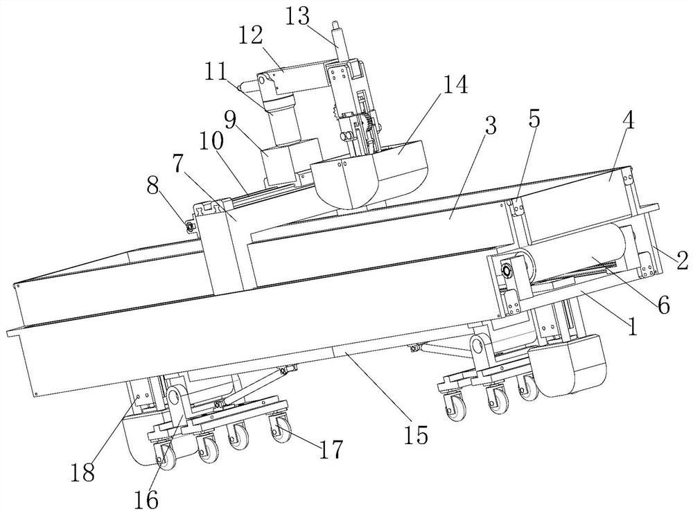
[0041] Such as figure 1 As shown, a material transfer device for highway engineering construction includes a first support plate 1, the second support plate 2 connected to the first support plate 1 and its two sides forms a U-shaped shell, and the top of the U-shaped shell is fixedly provided with a transfer material Both sides of the box 3 and the transfer box 3 are bolt-connected with a baffle plate 4, and a first stop is fixed between the baffle plate 4 and the transfer box 3 to make the baffle plate 4 rotate around the transfer box 3 Assemblies 5, the top of the first support plate 1 is fixedly provided with the first lateral horizontal displacement assembly 6, the output end of the first lateral horizontal displacement assembly 6 is fixedly provided with the first sliding seat 7, and one side of the first sliding seat 7 is fixedly provided There is a longitudinal horizontal displacement assembly 8, the output end of the longitudinal horizontal displacement assembly 8 is f...

Embodiment 2

[0043] On the basis of Example 1, such as figure 1 As shown, the number of support assemblies 18 is two, and the two support assemblies 18 are arranged symmetrically with the vertical midline of the base 15 as the axis of symmetry.

Embodiment 3

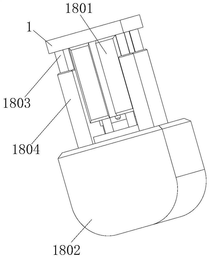
[0045] On the basis of Example 1, such as Figure 1-2 As shown, the support assembly 18 includes a biaxial cylinder 1801 fixedly arranged at the bottom of the first support plate 1, the output end of the biaxial cylinder 1801 is fixedly connected with a third support block 1802, and the top of the third support block 1802 is fixedly provided with a second A limiting rod 1803 , and a limiting cylinder 1804 for limiting the second limiting rod 1803 is movably disposed between the second limiting rod 1803 and the first support plate 1 .


PUM


Abstract

The invention relates to the technical field of road construction, and discloses a material transfer device for road engineering construction, comprising a first support plate, the first support plate and the second support plates connected to its two sides form a U-shaped shell, and the U-shaped The top of the shaped shell is fixedly provided with a transfer box, and both sides of the transfer box are bolt-connected with a baffle plate, and there is a fixed arrangement between the material baffle plate and the transfer box so that the baffle plate surrounds the transfer box Rotating first limit assembly, the top of the first support plate is fixed with a first lateral horizontal displacement assembly, the output end of the first lateral horizontal displacement assembly is fixed with a first slide seat, and the first slide One side of the seat is fixedly provided with a longitudinal and horizontal displacement assembly. The invention solves the problem that the general material transfer device cannot screen the coarse aggregate, so that the coarse aggregate with a smaller particle size will not enter the transfer box through the grab box, thereby avoiding the coarse aggregate with a smaller particle size. Aggregate mixing into concrete occurs.

Description

technical field [0001] The invention relates to the technical field of road construction, in particular to a material transfer device for road engineering construction. Background technique [0002] Highway engineering refers to the investigation, measurement, design, construction, maintenance and management of highway structures. Highway engineering structures include roadbeds, road surfaces, bridges, culverts, tunnels, drainage systems, safety protection facilities, greening and traffic monitoring facilities, as well as houses, workshops and other service facilities used for construction, maintenance and monitoring. In the process of highway construction, human handling is boring, time-consuming and labor-intensive, so material transfer devices are indispensable. However, the material transfer devices currently used in the market have a single structure and cannot screen coarse aggregates, making it possible during the concrete mixing process. Coarse aggregate with a cert...

Claims


Application Information

Patent Timeline
Patent Type & Authority Patents(China)
IPC IPC(8): B65G35/00B65G47/74B07B1/28B07B1/42B07B1/46B66C23/26B66C11/10B66C9/14B66C3/20B66C3/02
CPCB65G35/00B65G47/74B07B1/28B07B1/42B07B1/46B66C23/26B66C11/10B66C9/14B66C3/20B66C3/02
Inventor 范龙飞
Owner 赣州康大高速公路有限责任公司
Why Eureka
Try Eureka