Fixable translation crane for maintenance of equipment in cabin

An in-cabin, fixed technology, used in cranes, load hanging elements, walking bridge cranes, etc., can solve the problems of narrowness, inconvenient installation, and large space occupation, and achieves small space height, convenient installation, and occupation of the engine room. small space effect

Pending Publication Date: 2018-03-30
ZHEJIANG SHUANGNIAO MACHINERY
View PDF8 Cites 0 Cited by
  • Summary
  • Abstract
  • Description
  • Claims
  • Application Information

AI Technical Summary

Problems solved by technology

[0002] Usually, there are large gear boxes, large transmission shafts and other equipment in the engine room. Due to the huge quality of these devices and the height of the engine room above 700 meters, when it is necessary to repair and replace parts or perform necessary maintenance on the equipment in the engine room, it is necessary In order to remove the damaged parts from the cabin and put them on the ground, it is also necessary to lift the parts to be replaced on the ground and transport them into the cabin. It is not the best solution to install a gantry or cantilever spreader in a limited engine room. Both of them have columns, which are inconvenient to install and take up a lot of space.

Method used


Image

  • Fixable translation crane for maintenance of equipment in cabin
  • Fixable translation crane for maintenance of equipment in cabin
  • Fixable translation crane for maintenance of equipment in cabin

Examples


Embodiment Construction

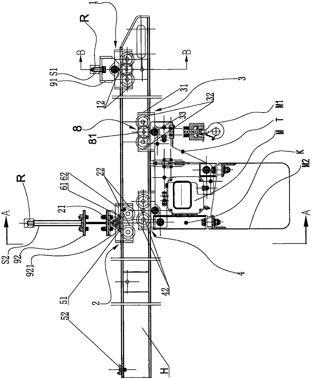
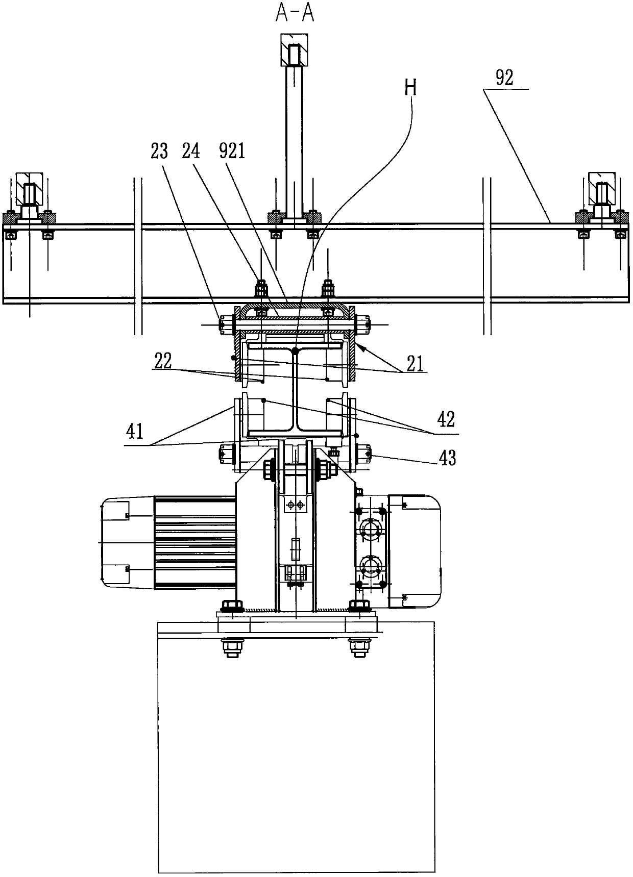
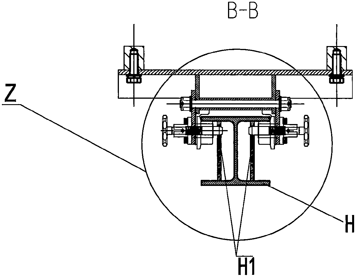
[0020] Fixed translational crane for equipment maintenance in the engine room, including two sets of upper trolley devices fixed under the roof of the engine room R, translation beam H, two sets of lower trolley devices, connecting frame T, chain electric hoisting crane M and storage chain Bag M2, wherein one set of upper trolley device 1 is located adjacent to the relatively low cabin door, the other set of upper trolley device 2 is located behind a set of upper trolley device 1, and the upper wing of the translational beam H is directly suspended and supported on a On the support wheel 12 of the upper trolley device 1 and the support wheel 22 of the other upper trolley device 2, the connecting frame T is located under the translation beam H, and the two sets of lower trolley devices are respectively slidingly fitted on the lower wings of the translation beam H , and a group of lower trolley devices 3 are connected to the front upper part of the connecting frame T, another set...


PUM


Abstract

The invention discloses a fixable translation crane for maintenance of equipment in a cabin. The fixable translation crane comprises a translation beam, a connecting frame located below the translation and a crane body arranged below the connecting frame. The upper wing of the translation beam is suspended and supported on supporting wheels of two sets of upper trolley devices, and two sets of lower trolley devices in sliding fit with the lower wing of the translation beam are arranged on the connecting frame. An advancing stop claw and a retreating stop claw are arranged on the other set of upper trolley device. An advancing stop check block and a retreating stop check block used for displacement limiting of the translation beam are arranged on the top face of the translation beam in a spaced manner. Two upper locating holes are formed in the upper portion of the translation beam in a spaced manner. Locking structures used for retreating prevention of the stretching-out translation beam and outward movement prevention of the return translation beam are arranged on one set of upper trolley device. Locking pins of the locking structures can selectively penetrate into the upper locating holes. Two lower lock holes are formed in the lower portion of the translation beam in a spaced manner. Sliding stop structures are arranged on one set of lower trolley device and can lock the lower trolley device to be fixed, and locking pins of the sliding stop structures can penetrate into the lower lock holes. By means of the above scheme, limiting and locking of the translation beam and sliding stop of the lower trolley devices are achieved.

Description

【Technical field】 [0001] The invention relates to a fixed translational crane for equipment maintenance in a nacelle, which is applied to the occasion of high-altitude hoisting of heavy objects in and out of the nacelle. 【Background technique】 [0002] Usually, there are large gear boxes, large transmission shafts and other equipment in the engine room. Due to the huge quality of these devices and the height of the engine room above 700 meters, when it is necessary to repair and replace parts or perform necessary maintenance on the equipment in the engine room, it is necessary In order to remove the damaged parts from the cabin and put them on the ground, it is also necessary to lift the parts to be replaced on the ground and transport them into the cabin. It is not the best solution to install a gantry or a cantilever spreader in a limited engine room. Both of them have columns, which are inconvenient to install and occupy a large space. 【Content of invention】 [0003] T...

Claims


Application Information

Patent Timeline
Patent Type & Authority Applications(China)
IPC IPC(8): B66C17/06B66C7/16
CPCB66C7/16B66C17/06
Inventor 盛嘉庆汪小东杨美芳
Owner ZHEJIANG SHUANGNIAO MACHINERY
Why Eureka
Try Eureka