
Vertical take-off and landing fixed-wing unmanned aerial vehicle

A vertical take-off and landing, fixed-wing technology, applied in vertical take-off and landing aircraft, rotorcraft, fuselage and other directions, can solve the problems of increasing the weight of the installation structure, insufficient overall rigidity and strength, reducing the overall weight, improving safety and stability, The effect of enhancing the overall stiffness strength

Pending Publication Date: 2020-10-30
SHANGHAI AUTOFLIGHT CO LTD
View PDF2 Cites 0 Cited by
  • Summary
  • Abstract
  • Description
  • Claims
  • Application Information

AI Technical Summary

Problems solved by technology

[0003] The technical problem to be solved by the present invention is to provide a vertical take-off and landing fixed-wing unmanned aerial vehicle in order to overcome the defects that the weight of the installation structure is increased and the overall rigidity is insufficient in the way that the lift arm is fixed on the wing through a mechanical structure.

Method used


Image

  • Vertical take-off and landing fixed-wing unmanned aerial vehicle
  • Vertical take-off and landing fixed-wing unmanned aerial vehicle
  • Vertical take-off and landing fixed-wing unmanned aerial vehicle

Examples


Embodiment 1

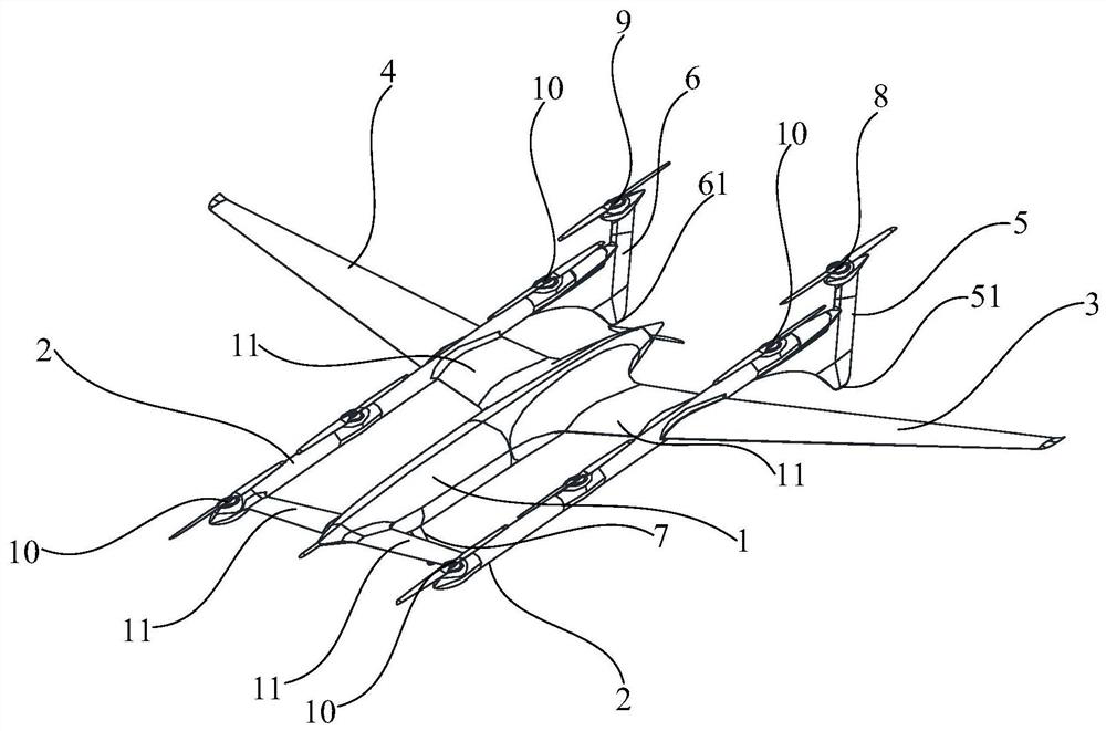
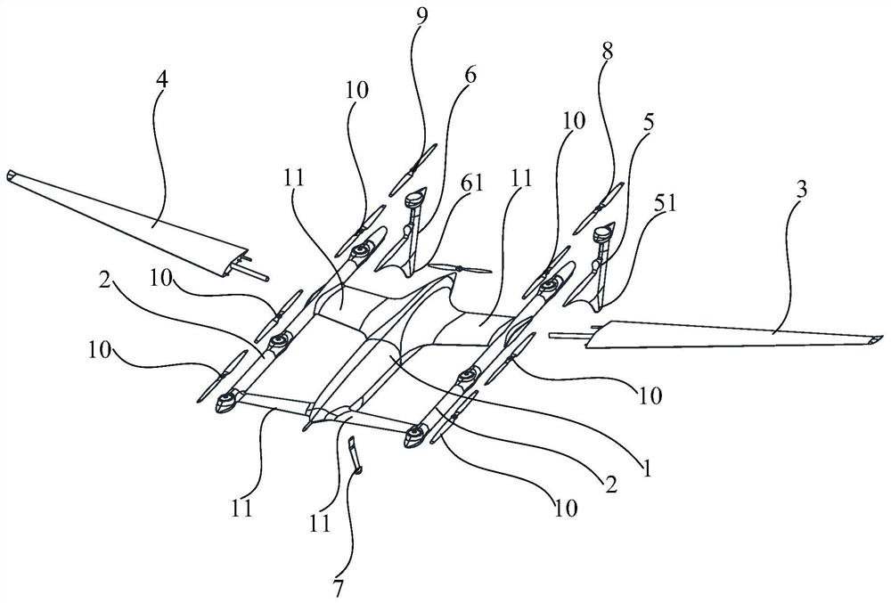
[0048] like figure 1 and figure 2 As shown, the vertical take-off and landing fixed-wing unmanned aerial vehicle of the embodiment of the present invention comprises fuselage 1 and two machine arms 2, and two machine arms 2 are respectively connected to the both sides of fuselage 1, and two machine arms 2 and machine arm The body 1 is integrally formed. The two arms 2 are respectively connected to both sides of the fuselage 1 and integrated with the fuselage 1, and the fuselage 1 is used to fuse the arms 2, so that the arm 2 does not need to be connected with the fuselage 1 through a mechanical mechanism, reducing The installation structure of the machine arm 2 reduces the overall weight of the vertical take-off and landing fixed-wing unmanned aerial vehicle and achieves the purpose of improving the flight time. At the same time, the two arms 2 are integrated with the fuselage 1, effectively enhancing the overall rigidity of the fuselage 1 and the arm 2, and greatly improvi...

Embodiment 2

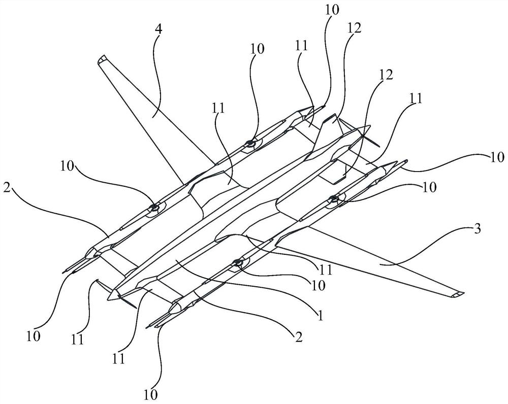
[0061] like image 3 and Figure 4 As shown, the structure of the vertical take-off and landing fixed-wing unmanned aerial vehicle of this embodiment and the same part of Embodiment 1 will not be repeated, and only the differences will be described. The vertical take-off and landing fixed-wing unmanned aerial vehicle also includes at least one vertical tail 12, the vertical tail 12 can be connected above the tail end of the fuselage 1, and the vertical tail 12 can also be connected below the tail end of the fuselage 1. The vertical tail 12 can respectively control the heading direction of the vertical take-off and landing fixed-wing UAV. The number of vertical tails 12 can be two, and the two vertical tails 12 are respectively connected above and below the tail end of the fuselage 1 .

[0062] When the vertical tail 12 is connected to the bottom of the tail end of the fuselage 1, the bottom of the vertical tail 12 can play a supporting role, so that the vertical take-off and...


PUM


Abstract

The invention discloses a vertical take-off and landing fixed-wing unmanned aerial vehicle which comprises a vehicle body and two vehicle arms, wherein the two vehicle arms are connected to the two sides of the vehicle body respectively, and the two vehicle arms and the vehicle body are integrally formed. According to the vertical take-off and landing fixed-wing unmanned aerial vehicle, the two vehicle arms and the vehicle body are integrated, the vehicle body is fused with the vehicle arms, and the mounting structures of the vehicle arms are reduced, so that the overall weight of the verticaltake-off and landing fixed-wing unmanned aerial vehicle is reduced, and the purpose of improving flight endurance is achieved. Meanwhile, the overall rigidity and strength of the vehicle bodyand thevehicle arms are enhanced, and the safety and stability of the vertical take-off and landing fixed-wing unmanned aerial vehicle are greatly improved.

Description

technical field [0001] The invention relates to a vertical take-off and landing fixed-wing unmanned aerial vehicle. Background technique [0002] The lift arm of the existing vertical take-off and landing fixed-wing unmanned aerial vehicle is fixed on the wing through a mechanical structure, and a compound wing vertical take-off and landing aircraft with patent publication number CN105539835A (application number: 201610030169.0) can be referred to . However, the way in which the lifting arm is fixed on the wing through a mechanical structure will increase the weight of the installation structure, and at the same time, the overall rigidity is insufficient. Contents of the invention [0003] The technical problem to be solved by the present invention is to provide a vertical take-off and landing fixed-wing unmanned aerial vehicle in order to overcome the defects that the weight of the installation structure is increased and the overall rigidity is insufficient in the way th...

Claims


Application Information

Patent Timeline
IPC IPC(8): B64C29/00B64C27/26B64C1/06B64C5/06B64C25/04
CPCB64C1/069B64C5/06B64C25/04B64C27/26B64C29/0008
Inventor 田瑜
Owner SHANGHAI AUTOFLIGHT CO LTD
Learn More