
Dust suppression device

A technology of electrical boxes and fog cannons, applied in lifting devices, vibration suppression adjustment, non-rotational vibration suppression, etc., can solve problems such as loud noise and vibration, and inconvenient dust suppression

Inactive Publication Date: 2020-10-30
李志成
View PDF7 Cites 2 Cited by
  • Summary
  • Abstract
  • Description
  • Claims
  • Application Information

AI Technical Summary

Problems solved by technology

[0003] At present, there are many kinds of dust suppression devices for construction sites on the market, but these dust suppression devices can only adjust the angle of the fog cannon up and down, and cannot conveniently rotate the fog cannon to suppress dust on the construction site in different directions, and the fog When the cannon is working, it will produce a lot of noise and vibration

Method used


Image

  • Dust suppression device
  • Dust suppression device
  • Dust suppression device

Examples


Embodiment 1

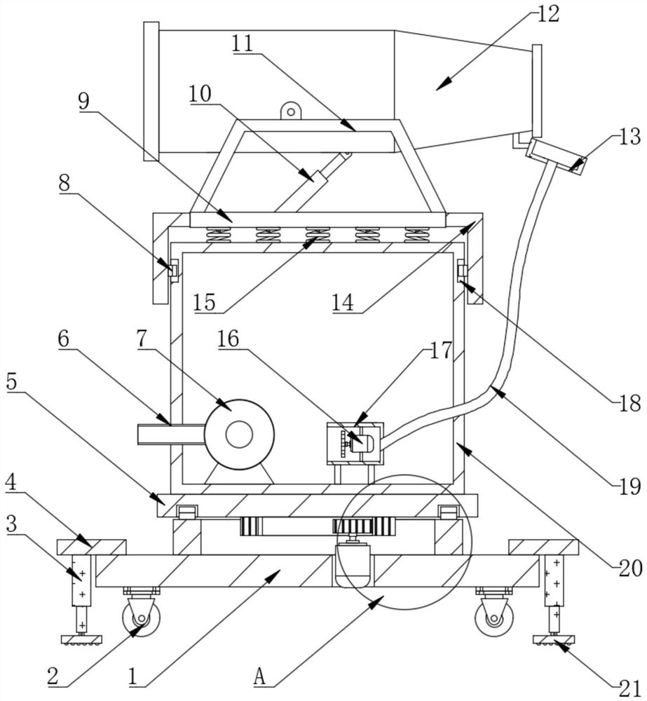
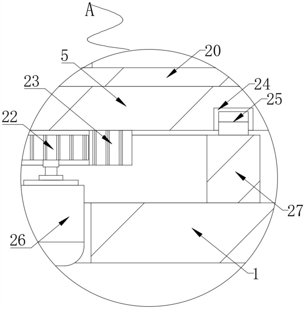
[0024] see Figure 1~2 , in an embodiment of the present invention, a dust suppression device includes a base 1, the four corners of the bottom of the base 1 are connected with moving wheels 2, and the top of the base 1 is provided with an electrical box 20, and the inside of the electrical box 20 is connected with a water pump 7, One side of the water pump 7 is connected with an external water pipe 6, and the top of the electrical box 20 is provided with a fog cannon support seat 9, and both sides of the top of the fog cannon support seat 9 are connected with a fog cannon support 11, and the top of the fog cannon support seat 9 is provided with a hydraulic pressure Push rod 10, one side of two fog cannon brackets 11 are connected with fog cannon 12, the top of base 1 is connected with support ring 27, the top of base 1 is provided with installation groove, and the interior of installation groove is provided with motor 26, The top of the support ring 27 is equipped with an ann...

Embodiment 2

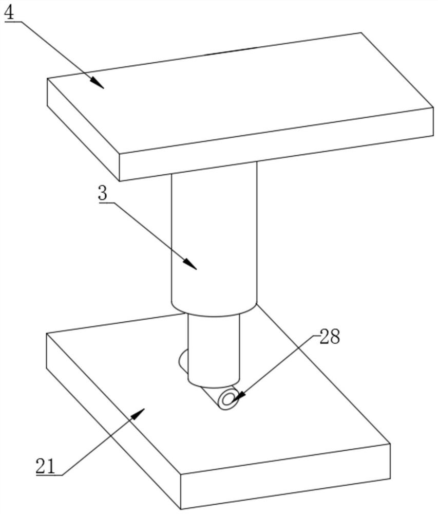
[0032] refer to figure 1 with 3 , a dust suppression device, compared with Embodiment 1, this embodiment also includes two reaction force plates 4 connected to both sides of the top of the base 1, and a hydraulic jack 3 is installed at the bottom of the reaction force plate 4, and the hydraulic jack 3 The bottom end is provided with a support plate 21.

[0033] Wherein, a hinge 28 is arranged between the hydraulic jack 3 and the support plate 21 , the hydraulic jack 3 and the support plate 21 are rotatably connected by the hinge 28 , and the bottom end of the support plate 21 is provided with an anti-slip pad.

[0034]Working principle: Due to the complex environment of the construction site, the base 1 may be dumped and shifted in position on the construction site. At this time, after the base 1 is moved to the designated position, the four hydraulic jacks 3 are turned on, so that the hydraulic jacks 3 drive the The supporting plate 21 that it connects moves toward the grou...


PUM


Abstract

The invention discloses a dust suppression device. The device comprises a base, wherein moving wheels are connected to four corners of the bottom end of the base; an electric box is arranged at the top of the base; a water pump is connected to the inner side of the electric box; an external water pipe is connected to one side of the water pump; a fog gun support base is arranged at the top of theelectric box; fog gun supports are connected to the two sides of the top end of the fog gun support base; and a hydraulic push rod is arranged at the top end of the fog gun support base. The device isprovided with a gear ring, a gear, a motor, an annular sliding groove, an annular sliding block, a supporting circular ring and a rotating seat; when a fog gun sprays for dust suppression, a rotating seat and the electrical box at the top end of the rotating seat can be conveniently rotated so as to allow the fog gun at the top of the electrical box to be rotated in a construction site to perform spraying dust suppression, so the dust suppression range of the dust suppression device is widened; and the fog gun does not need to be manually rotated, and an automation degree is high, so the working efficiency of the dust suppression device is improved.

Description

technical field [0001] The invention relates to the technical field of building construction equipment, in particular to a dust suppression device. Background technique [0002] Building construction refers to the production activities in the implementation stage of engineering construction, and it is the construction process of various buildings. Construction site dust refers to the dust raised on the construction site due to large-scale operations such as old building demolition, foundation excavation, bulldozing, filling, building material processing, personnel and vehicle activities during the construction process; construction site dust is mainly composed of PM2 .5, PM10 and other inhalable particles and solid large particles with a diameter greater than 10 microns; therefore, if the dust generated on the construction site cannot be properly treated, it will not only make the construction environment worse, but may also be harmful to the health of the builders cause a ...

Claims


Application Information

Patent Timeline
IPC IPC(8): B01D47/06B01D47/16B66F3/24F16F15/04F16F15/067
CPCB01D47/06B01D47/16B66F3/24F16F15/04F16F15/067
Inventor 李志成
Owner 李志成
Learn More