
Low-nitrogen combustion control system for coal water slurry circulating fluidized bed

A circulating fluidized bed and low-nitrogen combustion technology, which is applied in the direction of fluidized bed combustion equipment, fuel for combustion in a molten state, and combustion methods, etc., can solve problems such as high oxygen content in operation, environmental pollution, and high concentration of nitrogen oxides

Inactive Publication Date: 2020-10-27
青岛顺安热电有限公司
View PDF0 Cites 0 Cited by
  • Summary
  • Abstract
  • Description
  • Claims
  • Application Information

AI Technical Summary

Problems solved by technology

[0002] Circulating fluidized bed boilers use coal-based clean fuel coal-water slurry, which is an effective combustion method to reduce flue gas pollutants. However, during the actual operation of the boiler, the dynamic variables of the boiler are adjusted according to the external demand, especially in low-load operation. The oxygen content is too high, the ability to control nitrogen oxides is relatively low, and the concentration of nitrogen oxides generated is too high, around 300mg / Nm3, which seriously pollutes the environment. Therefore, we propose a low-nitrogen combustion based on coal-water slurry circulating fluidized bed The control system is used to solve the above problems

Method used


Image

  • Low-nitrogen combustion control system for coal water slurry circulating fluidized bed
  • Low-nitrogen combustion control system for coal water slurry circulating fluidized bed
  • Low-nitrogen combustion control system for coal water slurry circulating fluidized bed

Examples


Embodiment Construction

[0023] The following will clearly and completely describe the technical solutions in the embodiments of the present invention with reference to the accompanying drawings in the embodiments of the present invention. Obviously, the described embodiments are only some, not all, embodiments of the present invention. Based on the embodiments of the present invention, all other embodiments obtained by persons of ordinary skill in the art without making creative efforts belong to the protection scope of the present invention.

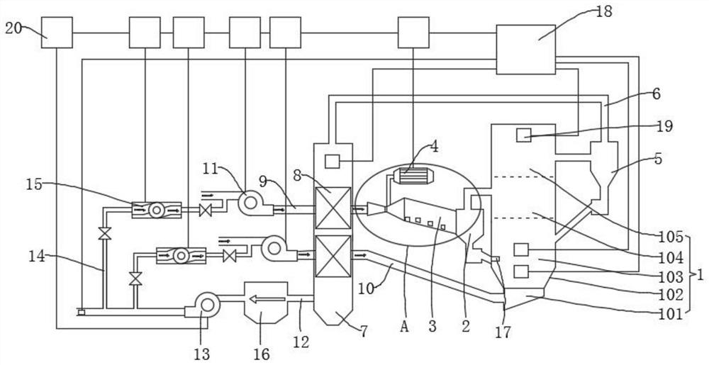
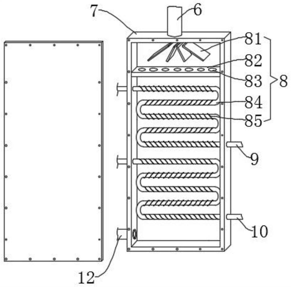
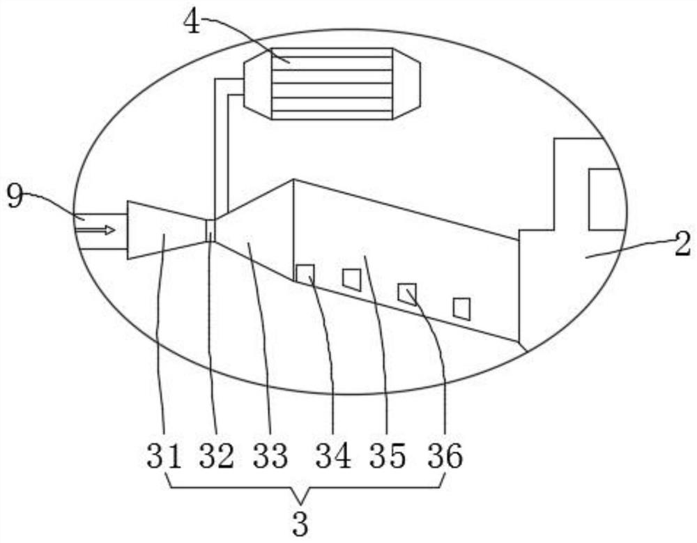
[0024] see Figure 1-3 , the present invention provides a technical solution: a low-nitrogen combustion control system based on a coal-water slurry circulating fluidized bed, including a fluidized bed 1, the bottom of the fluidized bed 1 is fixedly connected to a secondary air inlet pipe 10, and the fluidized bed 1 The middle part of the side wall is connected to the first separator 2, the first separator 2 is connected to the outlet end of the decomposition d...


PUM


Abstract

The invention discloses a low-nitrogen combustion control system for a coal water slurry circulating fluidized bed. The low-nitrogen combustion control system involves the fluidized bed, wherein the bottom of the fluidized bed is connected with a secondary air inlet pipe; the middle part of the side wall of the fluidized bed is connected with a first separator, the first separator is connected with a decomposing device, and the decomposing device is connected with a primary air inlet pipe and a slurry supply pump; the top of the fluidized bed is connected with a second separator, the second separator is connected with a smoke feeding pipe, the smoke feeding pipe is connected with a heat preservation box, and the heat preservation box is connected with a smoke exhaust pipe in sleeving mode;and the primary air inlet pipe and the secondary air inlet pipe are connected with the smoke exhaust pipe through circulating pipes, and circulating fans are arranged on the circulating pipes. The decomposing device pyrolyzes coal water slurry and primary inlet air under an anoxic condition to generate a large amount of reducing gas, and generated NOx is reduced into N2, so that the NOx is reduced; and the coal water slurry enters a main combustion area to be fully combusted with secondary inlet air, the reducing gas enters the fluidized bed through the first separator, and NOx generated in the main combustion area and the reducing gas are subjected to a reduction reaction, so that the emission concentration of the NOx is further reduced, and the low-nitrogen combustion performance is improved.

Description

technical field [0001] The invention relates to the technical field of coal-water slurry combustion, in particular to a low-nitrogen combustion control system based on a coal-water slurry circulating fluidized bed. Background technique [0002] Circulating fluidized bed boilers use coal-based clean fuel coal-water slurry, which is an effective combustion method to reduce flue gas pollutants. However, during the actual operation of the boiler, the dynamic variables of the boiler are adjusted according to the external demand, especially in low-load operation. The oxygen content is too high, the ability to control nitrogen oxides is relatively low, and the concentration of nitrogen oxides is too high, around 300mg / Nm3, which seriously pollutes the environment. For this reason, we propose a low-nitrogen combustion based on coal-water slurry circulating fluidized bed A control system is used to solve the above problems. Contents of the invention [0003] The object of the pres...

Claims


Application Information

Patent Timeline
Patent Type & Authority Applications(China)
IPC IPC(8): F23C10/10F23C10/18F23C10/20F23C10/28F23L15/00F23L9/00F23J15/02F23J15/06F23C9/06
CPCF23C9/06F23C10/10F23C10/18F23C10/20F23C10/28F23J15/02F23J15/06F23L9/00F23L15/00Y02E20/34
Inventor 王海峰张刚安亮王海涛于祥红孙鹏
Owner 青岛顺安热电有限公司
Learn More