Engine driving device

An engine-driven and passive technology, applied in the field of mechanical transmission, can solve the problems of inability to realize fast power engagement and disengagement switching, complicated mechanism, and increased overall weight

Pending Publication Date: 2020-10-27
ANHUI JIANGHUAI NAVISTAR DIESEL ENGINE CO LTD
View PDF0 Cites 2 Cited by
  • Summary
  • Abstract
  • Description
  • Claims
  • Application Information

AI Technical Summary

Problems solved by technology

[0002] In the prior art, the driving device is usually realized by using a multi-stage gear transmission mechanism, a belt transmission mechanism or a clutch mechanism. The application of these mechanisms cannot realize the fast engagement and disengagement switching of power, and the temporary failure in the transmission cannot be protected in time. , while the mechanism is relatively complex, the overall weight increases and the transmission efficiency is poor. In addition, the large volume and high complexity of the mechanism will lead to poor reliability and high failure rate of accessories

Method used


Image

  • Engine driving device
  • Engine driving device
  • Engine driving device

Examples


Embodiment Construction

[0030] The embodiments of the present invention are described in detail below. This embodiment is implemented on the premise of the technical solution of the present invention, and detailed implementation methods and specific operating procedures are provided, but the protection scope of the present invention is not limited to the following implementation example.

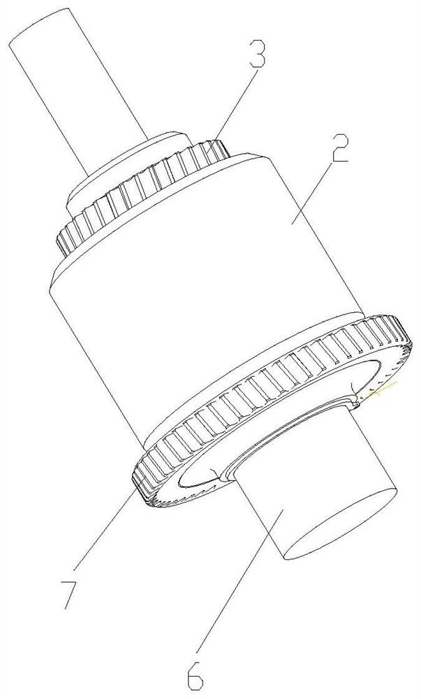
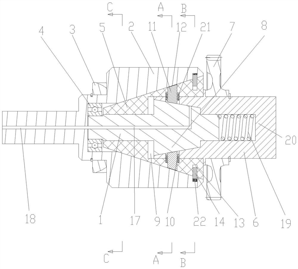
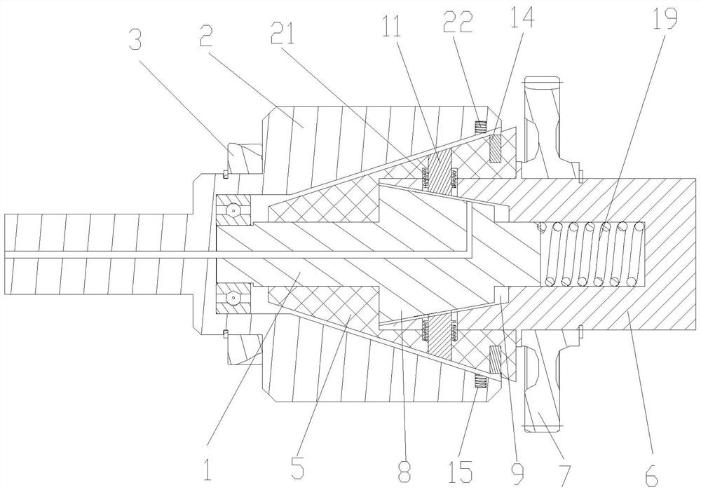
[0031] see Figure 1 to Figure 6 , the present embodiment discloses an engine driving device, including an active part and a passive part.

[0032] The driving part includes a driving shaft 1, a driving sleeve 2, and a driving wheel 3, and the axis direction of the driving shaft 1 is set as a left-right direction. The driving shaft sleeve 2 is rotatably fitted on the driving shaft 1, and the driving wheel 3 is fixedly sleeved on the left end of the driving shaft sleeve 2, and the inner hole of the driving shaft sleeve 2 is a tapered inner hole which is small on the left and large on the right. Wherein, the outer ...


PUM


Abstract

The invention discloses an engine driving device. The engine driving device comprises a driving part and a driven part, wherein the driving part comprises a driving shaft, a driving shaft sleeve, anda driving wheel; the inner hole of the driving shaft sleeve is a conical inner hole; the driven part comprises a driven shaft sleeve, and a driven wheel; the driven shaft sleeve is arranged on the driving shaft in a sleeving and sliding manner; the outer side wall of the left section of the driven shaft sleeve is matched with the shape of the conical inner hole of the driving shaft sleeve; a conical limited convex ring is arranged on the middle section of the driving shaft; a limited groove is formed in the inner hole of the driven shaft sleeve; a plurality of radial through holes are formed in the driven shaft sleeve; a short shaft is arranged in each radial through hole; a plurality of radial locking inner holes are also formed in the outer side wall of the left section of the driven shaft sleeve; a lock pin is arranged in each radial locking inner hole; a plurality of radial locking outer holes are formed in the wall of the conical inner hole of the driving shaft sleeve; and when adriven bearing is located at the left extreme position, the plurality of radial locking outer holes are connected to the plurality of radial locking inner holes in an abutting joint manner. The enginedriving device has the advantage that the quick connection or disconnection of the driving part and the driven part can be realized.

Description

technical field [0001] The invention relates to the technical field of mechanical transmission, in particular to an engine driving device. Background technique [0002] In the prior art, the driving device is usually realized by using a multi-stage gear transmission mechanism, a belt transmission mechanism or a clutch mechanism. The application of these mechanisms cannot realize the fast engagement and disengagement switching of power, and the temporary failure in the transmission cannot be protected in time. , At the same time, the mechanism is more complicated, the overall weight increases and the transmission efficiency is poor. In addition, the large volume and high complexity of the mechanism will lead to poor reliability and high failure rate of accessories. Contents of the invention [0003] The purpose of the present invention is to overcome the deficiencies of the prior art and provide a safe, reliable, stable working state and capable of quick engagement or disen...

Claims


Application Information

Patent Timeline
IPC IPC(8): F16D47/00F16D13/30F16D13/74F16D43/16
CPCF16D13/30F16D13/74F16D43/16F16D47/00
Inventor 葛锐李健朱文军胡志胜朱保林张军瑞辛雪军朱振东
Owner ANHUI JIANGHUAI NAVISTAR DIESEL ENGINE CO LTD
Why Eureka
Try Eureka