
Fixing device and mounting assembly comprising said fixing device

A technology for fixing devices and installing components, which is applied in the directions of transportation and packaging, antenna supports/installation devices, connecting components, etc., and can solve the problems of troublesome removal of installation modules, increased labor costs, and complexity

Pending Publication Date: 2020-10-27
FICO MIRRORS SA
View PDF6 Cites 0 Cited by
  • Summary
  • Abstract
  • Description
  • Claims
  • Application Information

AI Technical Summary

Problems solved by technology

This involves increased labor costs
On the other hand, the removal of the mounting modules also often becomes too cumbersome, requires complex and simultaneous operations, or involves designing the fixture as a single-use fixture

Method used


Image

  • Fixing device and mounting assembly comprising said fixing device
  • Fixing device and mounting assembly comprising said fixing device
  • Fixing device and mounting assembly comprising said fixing device

Examples


Embodiment Construction

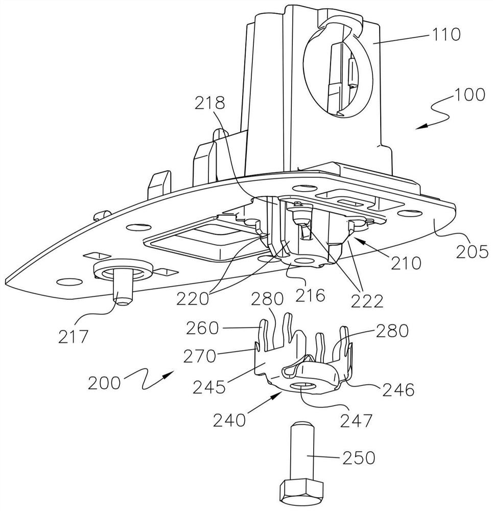
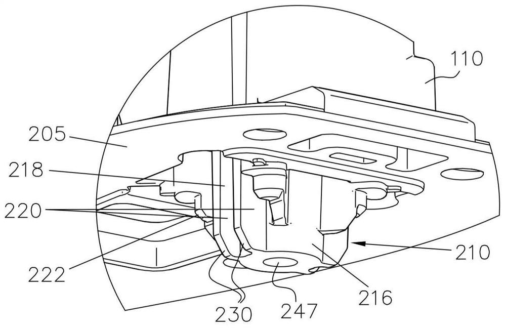
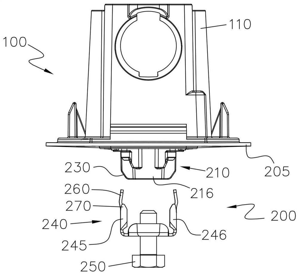
[0052] Disclosed below and in the accompanying drawings Figure 1 to Figure 14 Several non-limiting embodiments of the mounting assembly 100 of the present invention including a fixture are shown. In the illustrated embodiment, the securing device 200 is used to secure the mounting module (in this case the shark fin module 110 of the motor vehicle) to the vehicle surface (in this case the vehicle roof), such as Figure 1 to Figure 5 shown.

[0053] Fixture 200 includes base member 205 and bracket member 210 . The bracket member 210 has a first protruding portion 216 and the base member 205 has a second protruding portion 217 . Both protruding portions 216, 217 protrude downwards, such as figure 1 shown. In this embodiment, the first protruding portion 216 is made of aluminum and is part of the bracket member 210 . Other materials can be used. The first protruding portion 216 includes a chamfer 222, which will be described further below. The first protruding portion 216 ...


PUM


Abstract

The invention provides a fixing device and a mounting assembly comprising the said fixing device. The fixing device (200) comprises a base member (205); a bracket (210) with a portion (216) protrudingfrom the base member (205); a mounting bending part (240) attached to the protruding portion (216) and having at least one elastic pre-fixing leg (260), and at least one fixing bending leg (270); anda tightening member (250) for tightening the mounting bending part (240) to the bracket (210). The mounting bending part (240) and the protruding portion (216) can be arranged to clamp to each otherin a first relative position where the fixing bending leg (270) is between the base member (205) and the protruding portion (216); and in a second relative position where the pre-fixing elastic leg (260) is between the base member (205) and the protruding portion (216), and the fixing bending leg (270) is out of a position between the first relative position.

Description

technical field [0001] The present disclosure relates to a mounting assembly including a securing device for securing a mounting module to a vehicle surface. The mounting module may be, for example, an antenna module, and the vehicle surface may be, for example, a roof. Of course, other applications are also possible. The present disclosure also relates to a fixture included in the mounting assembly. Background technique [0002] Mounting a mounting module to a vehicle surface is always complex and time-consuming. In the specific case of the antenna module, an operator is required to place the antenna module in a position such that the screws in the antenna base support mate with corresponding holes formed in the vehicle roof panel. Typically an additional operator is required to insert and tighten screws from inside the vehicle into holes in the roof to attach the base support to the roof. This involves increased labor costs. On the other hand, removal of the mounting ...

Claims


Application Information

Patent Timeline
IPC IPC(8): F16B13/06H01Q1/12H01Q1/32
CPCF16B13/061H01Q1/1214H01Q1/3275B60R11/00B60R2011/0059H01Q1/12H01Q1/32
Inventor D·G·蒂莫内达
Owner FICO MIRRORS SA
Learn More