
Leakage plugging method for multi-layer casing damage section of oil well

A plugging method and oil well technology, which is applied in the direction of earthwork drilling, wellbore/well components, sealing/isolation, etc., which can solve the problem of long operation period, intubation that cannot ensure smooth insertion of bridge plugs, and inability to perform casing leveling. push process and other issues

Pending Publication Date: 2020-10-27
PETROCHINA CO LTD
View PDF5 Cites 1 Cited by
  • Summary
  • Abstract
  • Description
  • Claims
  • Application Information

AI Technical Summary

Problems solved by technology

[0004] (1) Chinese patent CN106014330A discloses a method for improving the success rate of chemical plugging of leaking casing damaged wells. The plugging material is to add quartz, calcite or marble particles to phosphate cement or aluminate cement, and use pre-cleaning , intermediate plugging and interval replacement methods to carry out large-scale leakage plugging, but the pressure test can only reach 15MPa, which cannot meet the plugging operation of old wells
[0005] (2) For multiple casing damage sections of the same well, plugging is often carried out one by one, but the general plugging operation will easily cause the plugging agent to only enter the casing damage section that is easier to enter, and other sections cannot be effectively sealed, so Multi-stage casing damage plugging leads to long operation cycle and short oil collection period
[0006] (3) Petroleum Drilling and Production Technology, 2012 Issue 02 "Research on Pipe Strings of Intubation Type Safety Plugging Technology" introduces the use of intubation type plugging strings. It can be injected with tubing but cannot be used for casing pushing process

Method used


Image

  • Leakage plugging method for multi-layer casing damage section of oil well
  • Leakage plugging method for multi-layer casing damage section of oil well
  • Leakage plugging method for multi-layer casing damage section of oil well

Examples


no. 1 approach

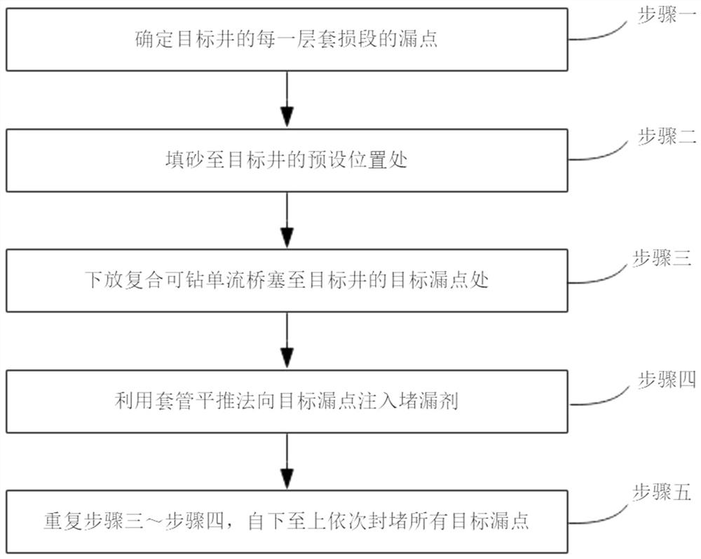
[0051] The first embodiment of the present invention relates to a plugging method for a multi-layer casing damaged section of an oil well, comprising the following steps:

[0052] Step 1, determining the leakage point of each casing damage section of the target well;

[0053] Step 2, filling sand to the preset position of the target well;

[0054] Step 3, lowering the composite drillable single-flow bridge plug to the target leakage point of the target well;

[0055] Step 4: Inject the plugging agent into the target leak point by using the casing horizontal push method;

[0056] Step 5, repeat steps 3 to 4, and block all target leaks sequentially from bottom to top.

[0057] According to the plugging direction from bottom to top, the casing damage section of each layer is plugged sequentially. According to the time sequence, the composite drillable single-flow bridge plugs installed are sequentially numbered as the first composite drillable single-flow bridge plug, and the s...

no. 2 approach

[0062] This embodiment relates to a plugging method for a multi-layer casing damage section of an oil well, including the following steps:

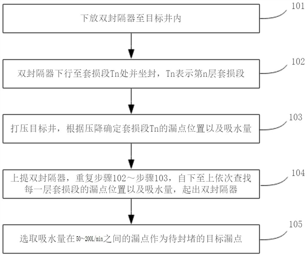
[0063] Step 1, determine the leakage point of each casing damage section of the target well, see figure 2 , including:

[0064] Step 101. lowering the double packer into the target well;

[0065] Step 102. The double packer goes down to the casing damage section Tn and sets, where Tn represents the casing damage section of the nth layer;

[0066] Step 103. Depress the target well, and determine the location of the leakage point and the water absorption of the casing damage section Tn according to the pressure drop;

[0067] Step 104. Lift up the double packer, repeat steps 102 to 103, search for the leakage point location and water absorption of each casing damage section from bottom to top, and pull out the double packer after the search is completed;

[0068] Step 105. Select a leak with a water absorption of 50-200 L / min as the tar...

no. 3 approach

[0095] In this embodiment, the following two wells have been tested using the plugging method of the multi-layer casing damage section of the oil well, specifically as follows:

[0096] The leak plugging operation was carried out in Well Luo X, which had 3 sections of casing damage after engineering logging.

[0097] The plugging resin plugging system is an epoxy resin plugging system, including E44 epoxy resin, triethylenediamine, and urotropine, and the three ratios are 100:12:1.

[0098] The plugging operation of the well is carried out, and the process is as follows:

[0099] Step 1: Double seal to confirm the leakage point and water absorption of each section;

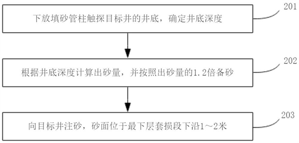
[0100] Step 2: Fill sand, the sand surface is located 1 meter below the lower edge of the casing damage section at the lowest end;

[0101] Step 3: Run the composite drillable single-flow bridge plug through the oil pipe operation, the lower edge of the bridge plug is located 1 meter above the upper edge of the ...


PUM


Abstract

The invention discloses a leakage plugging method for a multi-layer casing damage section of an oil well. The leakage plugging method comprises the steps that a leakage point of each layer of casing damage section of a target well is determined; a preset position of the target well is filled with sand; composite drillable uniflow bridge plugs are lowered to the target leakage points of the targetwell; a plugging agent is injected into the target leakage points by using a casing horizontal pushing method; and all the target leakage points are plugged in sequence from bottom to top. According to a rapid and effective leakage plugging process for the multi-section casing damage of the oil-water well, the multi-section casing damage oil-water well can be rapidly plugged, the operation periodis shortened, and meanwhile, the plugging surface can be controlled through an underground tool, the resin plugging agent consumption is reduced, the operation material cost is reduced, the multi-section casing damage leakage plugging effective rate is improved, the differentiation phenomenon of the plugging agent for multi-section general leakage plugging is avoided, the plugging efficiency is guaranteed, and the measure success rate is remarkably increased.

Description

technical field [0001] The invention belongs to the technical field of petroleum exploitation, and in particular relates to a leakage plugging method for multi-layer casing damage sections of oil wells. Background technique [0002] With the increase of production life of multi-reservoir oilfields, as well as the influence of geological conditions and engineering factors, casing damage and leakage of fluid outside the casing often occur, which affects the stable production of the oilfield and the smooth implementation of the development plan, and even causes production shutdown, seriously affecting the Effective water injection in reservoirs and enhancement of ultimate recovery. [0003] Currently, conventional leak plugging methods involve the following: [0004] (1) Chinese patent CN106014330A discloses a method for improving the success rate of chemical plugging of leaking casing damaged wells. The plugging material is to add quartz, calcite or marble particles to phosph...

Claims


Application Information

Patent Timeline
IPC IPC(8): E21B33/13E21B33/122E21B33/134
CPCE21B33/13E21B33/122E21B33/134
Inventor 郭钢薛建强李琼玮谷成义孙雨来杨立华王小勇卢文伟付彩利
Owner PETROCHINA CO LTD
Learn More