


Quick Research
Generate reliable direction feasibility study reports for your R&D in just a few steps.

Technical Q&A
Discover and master advanced knowledge NOW. Basics, ideas, possibilities, all at once.

Find Solutions
As an expert in R&D theories, this can generate solutions to your technical problems instantly.

Evaluate Feasibility
Analyze your overall solution with one click, know your potential R&D risks in advance.

Monitor Landscape
Get weekly tech updates, stay abreast of the latest tech innovations and key insights.
Grouting pipe reinforcing and grouting structure and construction method thereof
A grouting pipe and grouting technology, applied in the field of steel pipe grouting, can solve the problems of poor bearing effect of grouting pipe, poor output of grouting pipe, support of grouting pipe, etc.
- Summary
- Abstract
- Description
- Claims
- Application Information
AI Technical Summary
Problems solved by technology
Method used
Image

Examples
Embodiment 1
[0056] This embodiment discloses a grouting pipe reinforcement grouting structure.
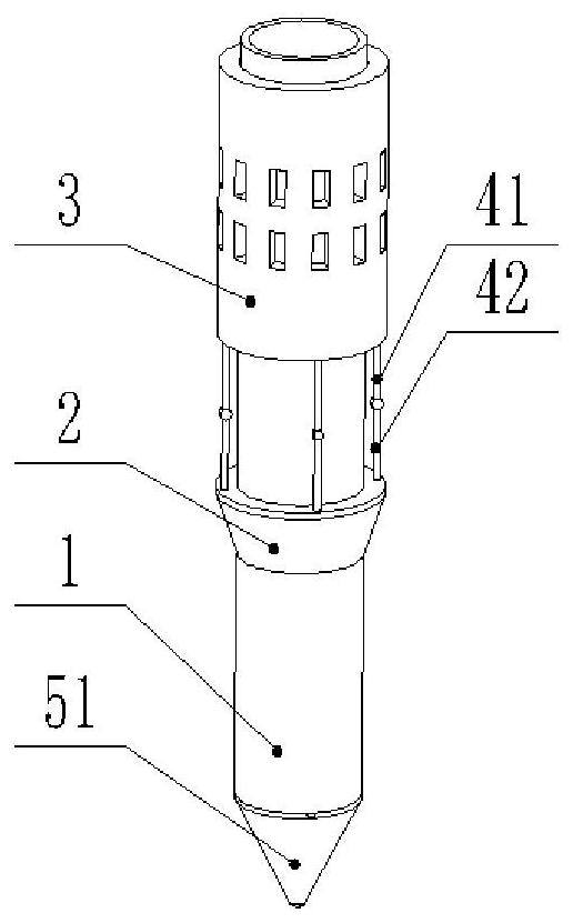
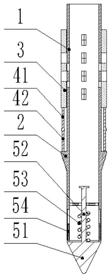
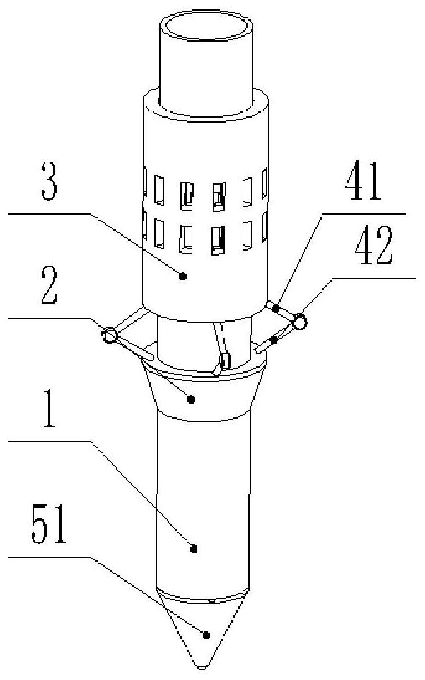
[0057] Such as figure 1 and figure 2 Shown: a grouting pipe reinforced grouting structure, including a grouting pipe 1, and a soil-breaking mechanism arranged on the grouting pipe 1; the soil-breaking mechanism includes a fixed part 2 fixedly arranged on the grouting pipe 1, coaxial The sliding pipe part 3 is sleeved on the grouting pipe 1 at a position above the fixed part 2 and is slidingly matched with the surface of the grouting pipe 1. When the sliding pipe part 3 slides along the surface of the grouting pipe 1 toward the fixed part 2, it breaks the soil It can expand toward the axial direction away from the grouting pipe 1 .
[0058] combine image 3 As shown: the outer surface of the sliding pipe part 3 is also provided with a grouting groove penetrating in the direction of the grouting pipe 1 and corresponding to the position of the grouting hole provided on the grouting pipe 1, an...
Embodiment 2
[0077] On the basis of the first embodiment, this embodiment further discloses a construction method for reinforcing a grouting structure with a grouting pipe.
[0078] Such as Figure 6 Shown: a kind of construction method of grouting pipe reinforcement grouting structure, it implements based on the grouting pipe structure in embodiment one, and it comprises the following steps when fixing the grouting pipe:
[0079] Step A: inject the grouting pipe into the set pre-injection hole until the grouting pipe reaches the predetermined installation position;
[0080] Step B: lifting the grouting pipe upwards, so that the conical block and the grouting pipe are separated to an interval arrangement under the force of the elastic component;
[0081] Step C: Push the sliding pipe part toward the fixed part, so that the soil-breaking component expands away from the axis of the grouting pipe to expand the soil layer around the pipe, and at the same time, the grouting groove and the grou...
Embodiment 3
[0085]On the basis of the second embodiment, this embodiment further discloses a positioning guide mechanism and a push rod 81 mechanism.
[0086] In the actual implementation process, the pre-injection hole 101 is a pre-opened "column" hole, and its overall shape corresponds to the grouting pipe 1, but the inner diameter will be larger than the outer diameter of the grouting pipe 1 (in order to facilitate installation and grouting) , which makes the grouting pipe 1 have a certain activity space in the pre-injection hole 101, and then makes it difficult for the grouting pipe 1 to be completely vertically injected or installed in the pre-injection hole 101, that is, the grouting pipe 1 will lean against In the pre-injection hole 101. On the one hand, the inclined arrangement of the grouting pipe 1 makes it difficult to output the slurry uniformly, which not only affects the output effect of the slurry, but also affects the supporting effect of the slurry on the grouting pipe 1;...
PUM
 Abstract
Description
Claims
Application Information
 - R&D Engineer
- R&D Manager
- IP Professional
- Industry Leading Data Capabilities
- Powerful AI technology
- Patent DNA Extraction
Browse by: Latest US Patents, China's latest patents, Technical Efficacy Thesaurus, Application Domain, Technology Topic, Popular Technical Reports.
© 2024 PatSnap. All rights reserved.Legal|Privacy policy|Modern Slavery Act Transparency Statement|Sitemap|About US| Contact US: help@patsnap.com