


Quick Research
Generate reliable direction feasibility study reports for your R&D in just a few steps.

Technical Q&A
Discover and master advanced knowledge NOW. Basics, ideas, possibilities, all at once.

Find Solutions
As an expert in R&D theories, this can generate solutions to your technical problems instantly.

Evaluate Feasibility
Analyze your overall solution with one click, know your potential R&D risks in advance.

Monitor Landscape
Get weekly tech updates, stay abreast of the latest tech innovations and key insights.
Cloth cutting method for garment manufacturing
A clothing manufacturing and fabric technology, which is applied in the field of fabric cutting for clothing manufacturing, can solve the problems of general safety and easy access to the limbs of operators, and achieve the effects of improving safety, preventing collisions with knives, and maintaining a stable structure.
- Summary
- Abstract
- Description
- Claims
- Application Information
AI Technical Summary
Problems solved by technology
Method used
Image

Examples
Embodiment 1
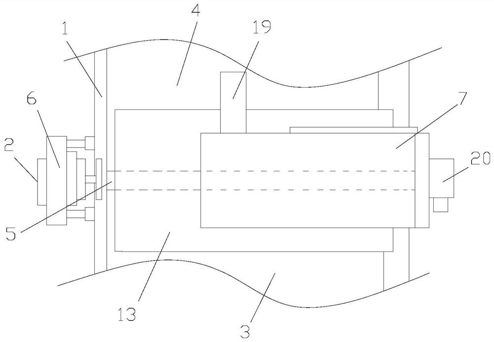
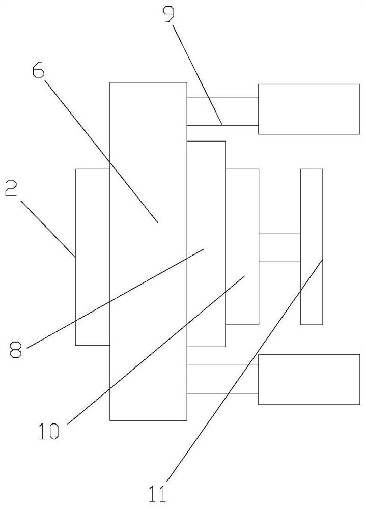
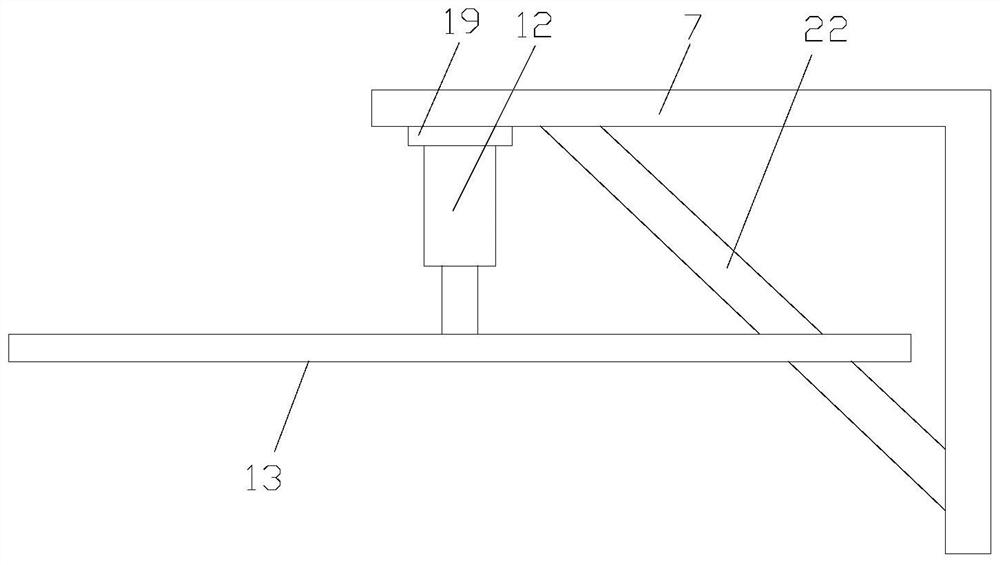
[0030] Such as Figure 1-4As shown, a cloth cutting machine for garment manufacturing includes a cutting table 1, a control device 2, a cutting device, a first conveying mechanism 3 and a second conveying mechanism 4, the control device 2 is a PLC, and the first conveying mechanism 3 and the second conveying mechanism 4 are installed on the cutting table 1, a gap 5 is formed between the first conveying mechanism 3 and the second conveying mechanism 4, the two ends of the gap 5 are respectively provided with first connecting plates 6 and the second connecting plate 7, the inside of the first connecting plate 6 is provided with a first electric guide rail 8 and a first electric push rod 9, an incremental encoder 10 is installed on the slider of the first electric guide rail 8, and the The rotating shaft of the incremental encoder 10 is connected with the measuring wheel 11, the control device 2 is located outside the first connecting plate 6, and the two ends of the first electr...
Embodiment 2
[0033] Such as Figure 1-6 As shown, a cloth cutting machine for garment manufacturing includes a cutting table 1, a control device 2, a cutting device, a first conveying mechanism 3 and a second conveying mechanism 4, the control device 2 is a PLC, and the first conveying mechanism 3 and the second conveying mechanism 4 are installed on the cutting table 1, a gap 5 is formed between the first conveying mechanism 3 and the second conveying mechanism 4, the two ends of the gap 5 are respectively provided with first connecting plates 6 and the second connecting plate 7, the inside of the first connecting plate 6 is provided with a first electric guide rail 8 and a first electric push rod 9, an incremental encoder 10 is installed on the slider of the first electric guide rail 8, and the The rotating shaft of the incremental encoder 10 is connected with a measuring wheel 11, and both the first connecting plate 6 and the measuring wheel 11 are hollow. The first connecting plate 6 ...
PUM
 Abstract
Description
Claims
Application Information
 - R&D Engineer
- R&D Manager
- IP Professional
- Industry Leading Data Capabilities
- Powerful AI technology
- Patent DNA Extraction
Browse by: Latest US Patents, China's latest patents, Technical Efficacy Thesaurus, Application Domain, Technology Topic, Popular Technical Reports.
© 2024 PatSnap. All rights reserved.Legal|Privacy policy|Modern Slavery Act Transparency Statement|Sitemap|About US| Contact US: help@patsnap.com