Camera module dispensing system based on turntable

A camera module and glue dispensing technology, which is applied to the surface coating liquid device, coating, etc., can solve the problems that the glue dispensing path cannot be corrected immediately and in real time, and it is difficult to correct the glue dispensing path in real time, so as to achieve the goal of eliminating Noise, quality-enhancing effects

Inactive Publication Date: 2020-10-27
SHINE OPTICS TECH CO LTD
View PDF8 Cites 10 Cited by
  • Summary
  • Abstract
  • Description
  • Claims
  • Application Information

AI Technical Summary

Problems solved by technology

[0006] The invention provides a camera module dispensing system based on a turntable, which solves the technical problem that the existing technology cannot corr...

Method used


Image

  • Camera module dispensing system based on turntable

Examples


Embodiment 1

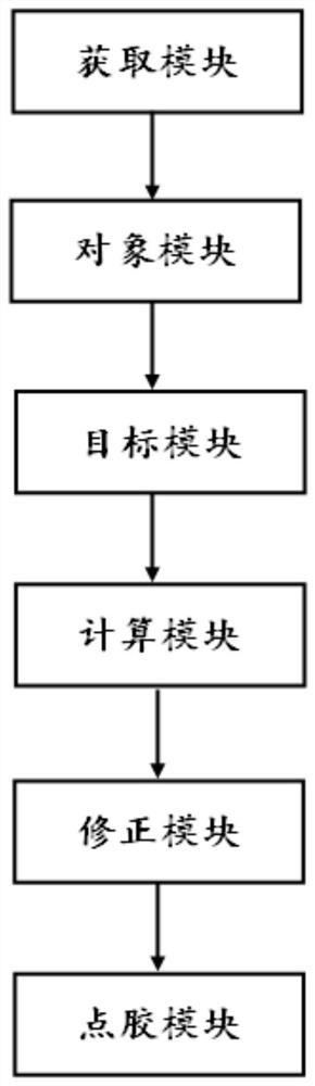
[0047] The embodiment of the camera module dispensing system based on the turntable of the present invention is basically as attached figure 1 shown, including:

[0048] The acquisition module is used to obtain dispensing path information according to the preset dispensing path;

[0049] The object module is used to obtain the object image coordinates of the object marking point in real time, the object marking point is located on the dispensing object, and the object image coordinates are the coordinates of the object marking point under the image coordinate system of the visual positioning camera;

[0050] The target module is used to obtain the target image coordinates of the target marking point in real time, the target marking point is located on the dispensing platform, and the target image coordinates are the coordinates of the target marking point under the image coordinate system of the visual positioning camera;

[0051] The calculation module is used to calculate t...

Embodiment 2

[0067] The only difference from Embodiment 1 is that the correction module further includes a filtering unit for filtering the dispensing path according to the second position information and the position information of the determined nodes. Specifically, the first step is to connect the point corresponding to the first position information of the undetermined node and the nearest definite node of the undetermined node into a first straight line according to the preset filter multiplier value, and fit the definite node into a second straight line . The second step is to calculate the angle between the first straight line and the second straight line, and increase the filter multiplier value when the angle is greater than the angle threshold. For example, calculating the angle between the first straight line and the second straight line includes: converting the position information of the determined node and the first position information of the undetermined node into Cartesian...


PUM


Abstract

The invention relates to the technical field of dispensing, in particular to a camera module dispensing system based on a turntable. The system comprises an acquisition module, an object module, a target module, a calculation module, a correcting module and a dispensing module. The acquisition module is used for acquiring dispensing path information according to a preset dispensing path; the object module is used for acquiring object image coordinates of object mark points in real time; the target module is used for acquiring target image coordinates of target mark points in real time; the calculation module is used for calculating the coordinate deviation amount of the object platform coordinates and the target platform coordinates under a platform coordinate system in real time; the correcting module is used for correcting the dispensing path in real time according to the coordinate deviation amount and updating the dispensing path to obtain an updated dispensing path; and the dispensing module is used for carrying out dispensing according to the updated dispensing path information. The technical problems in the prior art that the dispensing path cannot be corrected immediately in real time when the dispensing path is changed, and the deviation of the dispensing path cannot be corrected in real time are solved.

Description

technical field [0001] The invention relates to the field of dispensing technology, in particular to a camera module dispensing system based on a turntable. Background technique [0002] Glue dispensing, also known as sizing, gluing, glue pouring, and glue dropping, is to smear, fill, and drop electronic glue, oil, or other liquids on the product, so that the product can stick, fill, insulate, fix, Surface smoothness and other effects have been widely used in the field of electronic manufacturing. [0003] Usually, microfluids of ideal size, such as conductive epoxy resin, adhesive, etc., are placed on the preset positions of electronic components such as cameras and chips by using dispensing mechanical equipment, so as to achieve reliable connection between electronic components. Due to the factors of mechanical equipment itself and human operation, there may be a deviation between the position of the dispensing object on the dispensing platform and the preset target posit...

Claims


Application Information

Patent Timeline
IPC IPC(8): B05C5/02B05C11/10
CPCB05C5/02B05C11/10
Inventor 贺高明
Owner SHINE OPTICS TECH CO LTD
Why Eureka
Try Eureka