
Method for operating spinning mill installation, and spinning mill installation operated using method

A technology of equipment and feeding equipment, applied in the field of spinning mill equipment, can solve the problems of reduced productivity, inability to use mixing belt adjustment, high cost, etc.

Active Publication Date: 2020-10-23
特吕茨施勒集团欧洲公司
View PDF8 Cites 0 Cited by
  • Summary
  • Abstract
  • Description
  • Claims
  • Application Information

AI Technical Summary

Problems solved by technology

In addition, the products are placed manually on the corresponding feeders, so adjustments with mixing belts are not possible at all
This leads to an undesired stop-and-go operation of the hybrid belt, which is associated with a higher energy consumption and thus higher costs of the entire system due to the frequent acceleration and stopping of the hybrid belt
In addition, the productivity of the entire plant is reduced, which leads to loss of time in production
In particular, this places a burden on the mechanical structure of the hybrid belt device

Method used


Image

  • Method for operating spinning mill installation, and spinning mill installation operated using method
  • Method for operating spinning mill installation, and spinning mill installation operated using method
  • Method for operating spinning mill installation, and spinning mill installation operated using method

Examples


Embodiment Construction

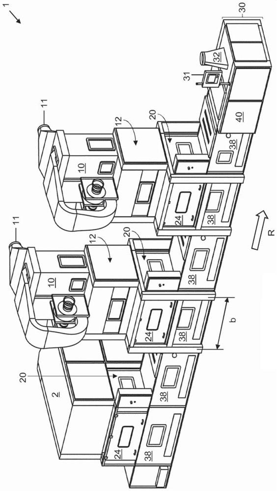
[0034] Figure 1 shows a bulk fiber mixing plant 1 as an example or part of a spinning mill plant.

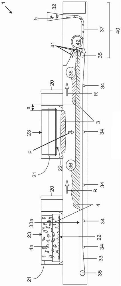
[0035] according to Figure 1a In the perspective view in FIG. 1, the bulk fiber mixing device 1 includes two feeders 10 in the example shown. Each feeder 10 has an inlet 11 for the incoming fiber air flow. The fiber air stream is opened in the respective relevant section 12 in a known manner. The loose fibers thus opened are fed to the correspondingly relevant weighing section 20. The weighing section 20 is located behind a cover plate 24 which is correspondingly located in the front here.

[0036] An additional box feeder 2 is arranged on the left side of the feeder 10, which also opens the incoming fiber material and delivers it to the relevant weighing section 20.

[0037] There is a receiving section 30 below the three weighing sections 20, 20, 20 here. The containing section 30 is used to transport the fiber material unloaded from the weighing section 20 toward the outlet 32 ...


PUM


Abstract

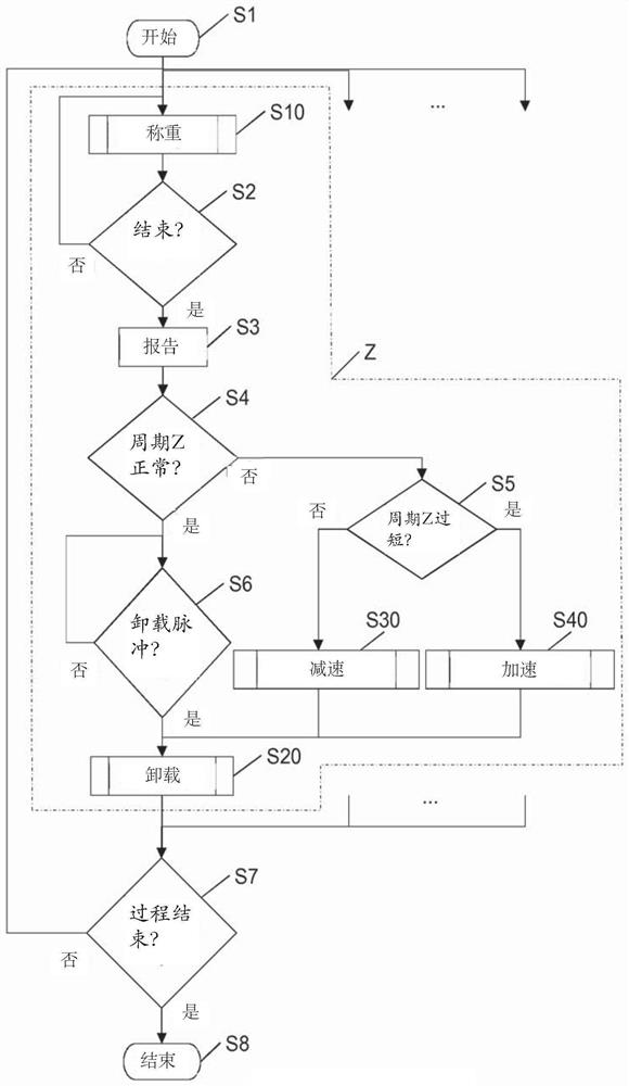
The invention relates to an operating method for a feeding installation (1) comprising a receiving device (30) to be fed and at least one feeding device (2, 10). The feeding device (2, 10) is designedto weigh fibrous material of a predetermined quantity in a cyclical manner and then to deliver the fibrous material to the receiving device (30). The method comprises a cycle (Z) including weighing the associated quantity of fibrous material in each feeding device (2, 10). Once a current cycle time dependent on or predetermined by the receiving device (30) has passed, minus a delivery time belonging to each of the at least one feeding devices (2, 10), a check is carried out as to whether each of the at least one feeding devices (2, 10) are capable of having weighed the associated quantity offibrous material and having delivered the fibrous material to the receiving device (30) when the current cycle time has passed. If each feeding device (2, 10) is capable of doing so, the associated quantity of fibrous material is delivered to the receiving device (30). Otherwise, the working speed of the feeding device(s) (2, 10) which is or are not capable of doing so is increased by a predetermined amount. A spinning mill installation (1) is constructed and designed to be operated according to the method.

Description

Technical field [0001] The invention relates to a method for operating spinning mill equipment and a spinning mill equipment operating by means of such a method. Background technique [0002] A spinning mill facility includes a number of individual spinning mill machines, which are arranged one after another in the production chain. One or more spinning mill machines provide material for one or more downstream spinning mill machines. For example, the bale opener supplies fibrous material to a cotton cleaner, for example in the form of a trash separator. The trash separator supplies the (pre)cleaned fibers to the cotton blender. The cotton blender supplies the mixed fibers to the fine cotton cleaner. The fine cleaning machine supplies the finely cleaned fibers to a plurality of carding machines. These cards provide fiber slivers to a relatively small number of draw frames. These draw frames supply the drawn fiber sliver to, for example, a relatively small number of sliver coi...

Claims


Application Information

Patent Timeline
IPC IPC(8): D01G13/00D01G23/04G01G13/18G01G17/02
CPCG01G13/18G01G17/02B65G43/08B65G65/42D01G13/00D01G23/045
Inventor 弗兰克·瓦科萨普艾克·塔门马克西米利安·马克思
Owner 特吕茨施勒集团欧洲公司
Learn More