
Outdoor low-voltage enclosed load isolation switch

An isolating switch and closed technology, which is applied in the field of outdoor low-voltage closed load isolating switches, can solve problems such as ineffective protection of lines and equipment, potential safety hazards of maintenance lines, and damage to knives or contacts.

Pending Publication Date: 2020-10-23
CHONGQING DEEPU ELECTRIC
View PDF0 Cites 1 Cited by
  • Summary
  • Abstract
  • Description
  • Claims
  • Application Information

AI Technical Summary

Problems solved by technology

[0002] Low-voltage fuse isolating switch is a commonly used device in low-voltage power distribution lines. The existing low-voltage fuse isolating switch mainly has the following problems: 1) The fuse is the core component of the low-voltage fuse isolating switch. The device is made of thin copper sheet with a narrow cross-section, and most of it is exposed to the natural environment during operation, and its time-current characteristics are easy to change due to the corrosion of acid rain and other natural environments. 2) The contact knife of the existing low-voltage fuse-type isolating switch cannot realize the self-locking function. During normal operation, the contact knife is easy to be accidentally separated from the holding position, resulting in Unnecessary power outage accidents; 3) The existing low-voltage fuse-type isolating switch does not have the function of load separation, and there are potential safety hazards when repairing the line, especially for large-capacity lines, the arc generated when the low-voltage fuse-type isolating switch is on-load. Severe ablation of the contact blade or contact surface, resulting in damage to the contact blade or contact

Method used


Image

  • Outdoor low-voltage enclosed load isolation switch
  • Outdoor low-voltage enclosed load isolation switch
  • Outdoor low-voltage enclosed load isolation switch

Examples


Embodiment Construction

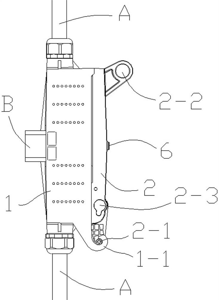
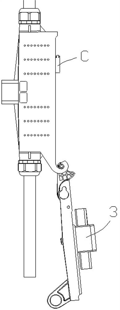
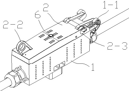
[0028] An outdoor low-voltage enclosed load isolating switch is structured as follows: the outdoor low-voltage enclosed load isolating switch is composed of a box body 1, a cover body 2, a fuse 3, two connection terminals 4 and two static contacts 5;

[0029] The fuse 3 is a knife-shaped fuse; the outer wall of the middle of the fuse 3 is connected to the inner side of the cover body 2;

[0030] The static contacts 5 are arranged on the bottom surface of the inner cavity of the box body 1 , and the positions of the two static contacts 5 are in one-to-one correspondence with the two contact blades on the fuse 3 ; the connection terminals 4 are arranged in the box body 1 . On the bottom surface of the cavity, the two terminals 4 are isolated from each other; the terminal 4 includes a contact connection end and a wire connection end, the contact connection end is electrically connected with the static contact 5, and the two connection terminals 4 are connected with the two static ...


PUM


Abstract

The invention provides an outdoor low-voltage closed load isolation switch. The switch is composed of a box body, a cover body, a fuse, two wiring terminals and two static contacts, wherein the middleof the fuse is connected with an inner side surface of the cover body, the static contact is arranged on a bottom surface of the inner cavity of the box body, the wiring terminal is arranged on the bottom surface of the inner cavity of the box body, a contact connecting end of the wiring terminal is electrically connected with the static contact, a wire connecting end of the wiring terminal is used for connecting an external wire, the box body is provided with a hole channel, and the wire connecting end is communicated with the outside through the hole channel. When the cover body seals an opening part of the box body, the contact knife on the fuse is inserted into an elastic slot of the static contact, and the box body and the cover body are made of insulating materials. The outdoor low-voltage closed type load isolation switch is advantaged in that according to the scheme, all components of the isolation switch can be packaged in the shell, a metal piece on the isolation switch is protected, and the foreign matter can be effectively prevented from being connected with the isolation switch in a lap joint mode.

Description

technical field [0001] The invention relates to an isolation switch, in particular to an outdoor low-voltage enclosed load isolation switch. Background technique [0002] The low-voltage fuse disconnector is a common device in low-voltage distribution lines. The existing low-voltage fuse disconnector mainly has the following problems: 1) The fuse is the core component of the low-voltage disconnector, and the existing low-voltage disconnector has the following problems: The device is made of thin copper sheet with a narrow cross-section, which is mostly exposed to the natural environment during operation, and its time-current characteristics are easily changed due to the corrosion of the natural environment such as acid rain. 2) The contact blade of the existing low-voltage fused disconnector cannot realize the self-locking function. During normal operation, the contact blade is easily separated from the holding position accidentally, resulting in Unnecessary power outages; ...

Claims


Application Information

Patent Timeline
IPC IPC(8): H01H31/02H01H31/12H01H85/045H01H85/32H01H85/54
CPCH01H31/023H01H31/12H01H85/0456H01H85/32H01H85/54
Inventor 吴文军杨靖雯张军强蒋婷
Owner CHONGQING DEEPU ELECTRIC
Learn More