
Phase change heat storage box structure

A phase change heat storage and box technology, which is applied to heat storage equipment, indirect heat exchangers, heat exchanger types, etc., can solve the problems of difficulty in taking out phase change materials, phase separation, and reduced heat storage capacity.

Pending Publication Date: 2020-10-23
暖冰(无锡)新材料科技有限公司
View PDF0 Cites 0 Cited by
  • Summary
  • Abstract
  • Description
  • Claims
  • Application Information

AI Technical Summary

Problems solved by technology

[0002] The phase change heat storage material may have phase separation after long-term operation, resulting in a decrease in heat storage capacity, and it is difficult to remove the phase change material from the heat storage box

Method used


Image

  • Phase change heat storage box structure
  • Phase change heat storage box structure

Examples


Embodiment Construction

[0009] The present invention will be further described below in conjunction with the accompanying drawings and embodiments.

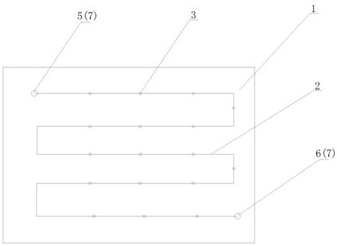
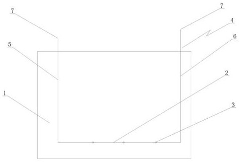
[0010] See figure 1 , figure 2 , a phase change heat storage box structure, which includes a phase change heat storage box 1, a pipeline 2 is arranged at the inner bottom of the phase change heat storage box 1, an air outlet 3 is arranged on the pipeline 2, and the pipeline 2 is connected to a blowing and suction device 4. Since the bottom of the phase change heat storage tank is equipped with a pipeline, the pipeline is provided with an air outlet, and the pipeline is connected to the blowing device. After a period of operation, the high-pressure gas from the outside is blown into the tank, and the steam drum is free from liquid material. Regular operation, fully stir and mix the phase change material again, prevent phase change material phase separation in the heat storage box, effectively ensure the heat storage capacity of the heat storage box, an...


PUM


Abstract

The invention provides a phase change heat storage box structure. The heat storage and release capability of a phase change heat storage device can recover, the heat storage capability of a heat storage box body is effectively ensured, and it is ensured that phase change materials in the heat storage box body can be conveniently taken out. The phase change heat storage box structure comprises thephase change heat storage box body and is characterized in that a pipeline is arranged at the inner bottom of the phase change heat storage box body; the pipeline is provided with a gas outlet; one end of the pipeline is connected with a gas outlet vertical pipe; the other end of the pipeline is connected with a gas inlet vertical pipe; a gas outlet is formed in the gas outlet vertical pipe; a gasinlet is formed in the gas inlet vertical pipe; and cyclic gas blowing and gas discharging on the pipeline are formed.

Description

technical field [0001] The invention relates to the technical field of application of phase-change heat storage materials, in particular to an improved structure of a phase-change heat storage tank. Background technique [0002] The phase-change heat storage material may have phase separation after long-term operation, resulting in a decrease in heat storage capacity, and it is difficult to remove the phase-change material from the heat storage box. Contents of the invention [0003] In view of the above technical problems, the present invention provides a phase change heat storage box structure, which can restore the heat storage capacity of the phase change heat storage equipment, effectively ensure the heat storage capacity of the heat storage box, and ensure the convenience of the phase change material in the heat storage box. take out. [0004] Its technical solution is as follows: a phase-change heat storage tank structure, which includes a phase-change heat storage...

Claims


Application Information

Patent Timeline
Patent Type & Authority Applications(China)
IPC IPC(8): F28D20/02B01F13/02B01F33/40
CPCF28D20/02B01F33/4094Y02E60/14
Inventor 王灵坚
Owner 暖冰(无锡)新材料科技有限公司
Learn More