A pressure relief direct acting relief valve

A direct-acting overflow valve and pressure relief technology, which is applied to valve devices, safety valves, balance valves, etc., can solve the problems of short service life, labor consumption, cost waste, etc.

Active Publication Date: 2022-02-11
WUHAN BOSITE VALVE GRP
View PDF12 Cites 0 Cited by
  • Summary
  • Abstract
  • Description
  • Claims
  • Application Information

AI Technical Summary

Problems solved by technology

[0003] During the use of modern direct-acting relief valves, because the pressure regulating spring is in a compressed state for a long time, the spring has a certain elastic deformation, resulting in unstable elastic force of the spring, affecting the overflow progress, resulting in poor overflow effect and stable At the same time, because the pressure regulating screw is not protected, moisture and dust in the air enter the screw, causing the screw to be corroded and rusted by the moisture in the air, resulting in a short service life of the device and a waste of cost. In addition, because the valve is often Closed, when the internal components of the device are damaged, it is inconvenient to disassemble and repair. During the repair, a large amount of labor is required to consume workers, which affects the progress of the repair, resulting in difficult repairs and labor waste. A pressure relief direct-acting relief valve is now introduced.

Method used


Image

  • A pressure relief direct acting relief valve
  • A pressure relief direct acting relief valve
  • A pressure relief direct acting relief valve

Examples


Embodiment Construction

[0024] The following will clearly and completely describe the technical solutions in the embodiments of the present invention with reference to the accompanying drawings in the embodiments of the present invention. Obviously, the described embodiments are only some, not all, embodiments of the present invention. Based on the embodiments of the present invention, all other embodiments obtained by persons of ordinary skill in the art without making creative efforts belong to the protection scope of the present invention.

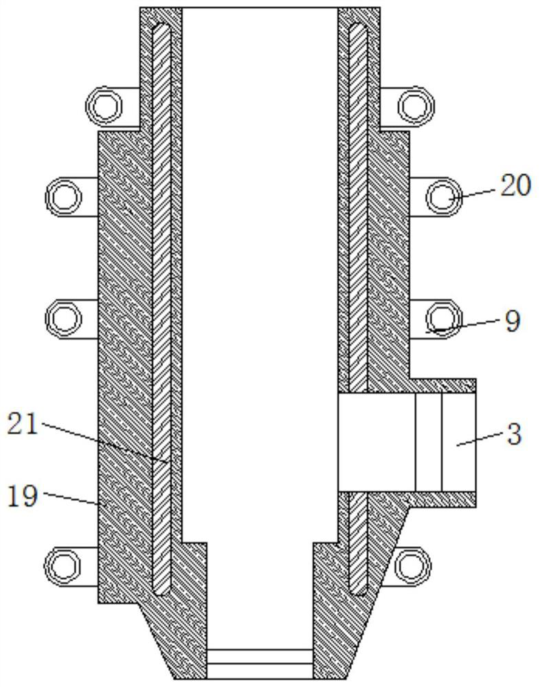
[0025] see Figure 1-5, a pressure relief direct-acting relief valve, comprising a first housing 1, a fixed block 13 is fixedly sleeved on the top end of the inner cavity of the first housing 1, and a pressure adjusting screw 12 is sleeved inside the fixed block 13 to adjust One end of the pressure screw 12 extends to the bottom of the fixed block 13 and is movably connected with the transmission block 10, and the bottom surface of the transmission block 10 is...


PUM


Abstract

The invention relates to the technical field of valves, and discloses a pressure relief direct-acting relief valve, which includes a first shell, a fixed block is fixedly sleeved on the top end of the cavity of the first shell, and an adjusting block is screwed inside the fixed block. One end of the pressure-adjusting screw extends to the bottom of the fixed block and is movably connected with the transmission block, and the bottom surface of the transmission block is fixedly connected with the pressure-regulating spring. In the present invention, through the cooperation of elastic parts, sliders, guide rails, linkage rods and connecting plates, the connecting plate drives the linkage rod to move, the linkage rod drives the slider to move on the guide rail, and the slider moves to compress the elastic parts to generate elastic force. The elastic force drives the connecting plate to move to buffer the pressure of the pressure regulating spring, avoiding that the pressure regulating spring is in a compressed state for a long time, and the spring has a certain elastic deformation, resulting in unstable elastic force of the spring, affecting the overflow progress, resulting in poor overflow effect, The problem of poor stability, improve the overflow effect while ensuring the stability of the overflow.

Description

technical field [0001] The invention relates to the technical field of valves, in particular to a pressure relief direct-acting overflow valve. Background technique [0002] The direct-acting relief valve is mainly composed of a valve body, a valve core, a pressure regulating spring and a pressure regulating screw. Under normal conditions, the valve core is tightly attached to the valve seat under the action of the pressure regulating spring. It is blocked, so the relief valve is normally closed. When the relief valve is connected to the system, the hydraulic oil will generate a force on the valve core. The direction of the force is opposite to the direction of the spring force. When the oil acts When it is greater than the spring force, the valve core opens, and the oil flows back to the tank from the overflow port. The spring force increases with the increase of the opening of the overflow valve until it is balanced with the hydraulic force. When the overflow valve starts ...

Claims


Application Information

Patent Timeline
Patent Type & Authority Patents(China)
IPC IPC(8): F16K17/04
CPCF16K17/04F16K17/0433
Inventor 徐兴勇
Owner WUHAN BOSITE VALVE GRP
Why Eureka
Try Eureka