
Discharging valve

A blanking and valve body technology, applied in the direction of lift valve, valve details, valve device, etc., can solve the problems of inability to control the size of the material flow, adjust the size of the material blanking, and low production efficiency.

Inactive Publication Date: 2020-10-23
NANJING KISEN INT ENG
View PDF0 Cites 0 Cited by
  • Summary
  • Abstract
  • Description
  • Claims
  • Application Information

AI Technical Summary

Problems solved by technology

[0002] Cement is a common building material. When the cement plant is producing cement, the upper part of the feed inlet of the external circulation vertical mill or roller press that grinds raw material or cement internally is equipped with a discharge valve to control the on-off of the powder. , Most of the existing feeding valves use rod valves or pneumatic gate valves. However, rod valves and pneumatic gate valves cannot control the size of the material flow, and the valve opening can only be fully open or fully closed. The discharge volume of follow-up equipment such as roller presses is used to adjust the discharge volume of materials in real time. Once the feed volume of subsequent equipment such as vertical mills or roll presses is greater than the discharge volume, the excess materials will overflow. At this time, only It can be closed and shut down, which will lead to the interruption of the entire preparation process, resulting in low production efficiency, which needs further improvement

Method used


Image

  • Discharging valve
  • Discharging valve

Examples


Embodiment Construction

[0009] Unless otherwise defined, the technical terms or scientific terms used in the present invention shall have the usual meanings understood by those skilled in the art to which the present invention belongs. "First", "second" and similar words used in the present invention do not indicate any order, quantity or importance, but are only used to distinguish different components. "Comprising" or "comprising" and similar words mean that the elements or items appearing before the word include the elements or items listed after the word and their equivalents, without excluding other elements or items. Words such as "connected" or "connected" are not limited to physical or mechanical connections, but may include electrical connections, whether direct or indirect. "Up", "Down", "Left", "Right" and so on are only used to indicate the relative positional relationship. When the absolute position of the described object changes, the relative positional relationship may also change acc...


PUM


Abstract

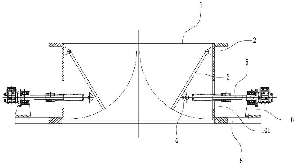
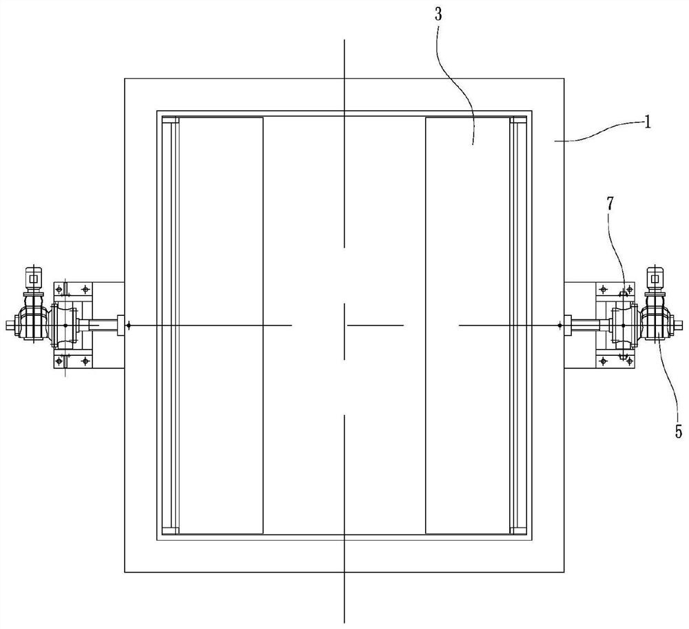
The invention discloses a discharging valve. The discharging valve comprises a valve body; two adjusting assemblies which are diagonally arranged are arranged on the valve body, each adjusting assembly comprises a valve plate, a first hinge support, a second hinge support, an electric cylinder, a base and a third hinge support, the first hinge supports are fixed to the inner wall of the valve body, the valve plates are arranged in the valve body, the upper ends of the valve plates are rotationally arranged in the first hinge supports, the second hinge supports are fixed to the outer sides of the lower ends of the valve plates, the bases are arranged outside the valve body, the third hinge supports are fixed to the upper sides of the bases, the electric cylinders are arranged on the side face of the valve body in a penetrating mode, the telescopic ends of the electric cylinders are rotationally connected into the second hinge supports, and the fixed ends of the electric cylinders are rotationally connected into the third hinge supports. According to the discharging valve, stepless control over the opening degree of the valve is achieved, the material flow can be adjusted in real time according to needs, the opening degree of the valve can be adjusted according to the discharging amount of follow-up equipment such as a vertical mill or a roller press so as to adjust the discharging amount, continuous and stable operation of the whole preparation process is guaranteed, and then the production efficiency is improved.

Description

technical field [0001] The invention relates to a feeding valve. Background technique [0002] Cement is a common building material. When the cement plant is producing cement, the upper part of the feed inlet of the external circulation vertical mill or roller press that grinds raw material or cement internally is equipped with a discharge valve to control the on-off of the powder. , Most of the existing feeding valves use rod valves or pneumatic gate valves. However, rod valves and pneumatic gate valves cannot control the size of the material flow, and the valve opening can only be fully open or fully closed. The discharge volume of follow-up equipment such as roller presses is used to adjust the discharge volume of materials in real time. Once the feed volume of subsequent equipment such as vertical mills or roll presses is greater than the discharge volume, the excess materials will overflow. At this time, only Can shut down and stop, and then cause the interruption of t...

Claims


Application Information

Patent Timeline
IPC IPC(8): F16K1/20F16K31/02
CPCF16K1/2007F16K1/2021F16K31/02
Inventor 张军赵俊
Owner NANJING KISEN INT ENG
Learn More