
Flexible profiling jig

A flexible and fixture technology, applied in the direction of chucks, manufacturing tools, manipulators, etc., can solve the problems of easily damaged product surface, the fixture does not have a correcting effect, and cannot be compatible with clamping work at the same time, so as to avoid surface damage.

Active Publication Date: 2020-10-23
安徽聚鼎智能装备制造有限公司
View PDF6 Cites 3 Cited by
  • Summary
  • Abstract
  • Description
  • Claims
  • Application Information

AI Technical Summary

Problems solved by technology

[0002] In the field of mechanical equipment manufacturing technology, research on equipment with high intelligence and high work efficiency is the ideal goal that manufacturers have been pursuing. Among them, major manufacturers will directly or indirectly carry out processes such as product turnover, polishing and painting, surface cleaning or drying and labeling. Therefore, assembly line-related devices are needed to assist the orderly implementation of the above-mentioned process links. When it comes to fixture equipment that is in direct contact with various products of different shapes, sizes, and properties, after research in this field, it is found that the columnar products that exist in the market are mostly straight, semicircular, and V-shaped. The fixture cannot be compatible with the clamping work of products of different shapes and sizes at the same time; the contact surface between the fixture and the product surface is in line contact, which is easy to damage the surface of the product; the fixture does not have the function of correcting deviation, and it is easy to cause the product to fall.

Method used


Image

  • Flexible profiling jig
  • Flexible profiling jig
  • Flexible profiling jig

Examples


Embodiment Construction

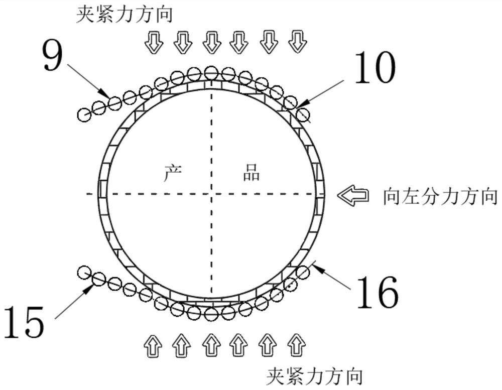
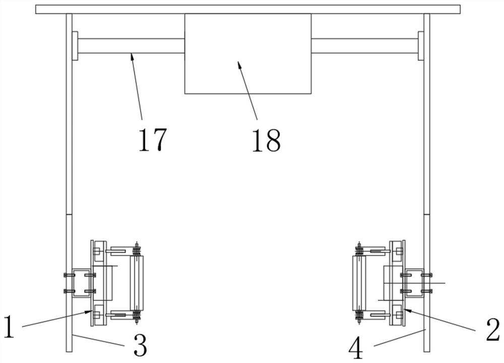
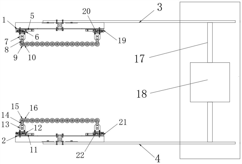
[0027] The technical solutions in the embodiments of the present invention will be clearly and completely described below in conjunction with the embodiments of the present invention. Apparently, the described embodiments are only some of the embodiments of the present invention, not all of them. Based on the embodiments of the present invention, all other embodiments obtained by persons of ordinary skill in the art without creative efforts fall within the protection scope of the present invention.

[0028] Such as Figure 1-7As shown, the flexible profiling fixture includes a first fixture bottom plate 1 and a second fixture bottom plate 2. The first fixture bottom plate 1 is fixed on the first jig arm 3 by several screws, and the second fixture bottom plate 2 is fixed on the second fixture bottom plate by several screws. On the clamp arm 4, the first slide rail 5 and the first slide block 6 are installed on the first clamp base plate 1, and the first connecting plate 7 is fi...


PUM


Abstract

The invention discloses a flexible profiling jig comprising a first jig baseplate and a second jig baseplate. The first jig baseplate is fixed to a first clip arm by a plurality of screws, and the second jig baseplate is fixed to a second clip arm by a plurality of screws; a first sliding rail and a first sliding block are installed on the first jig baseplate, and a first connecting plate is fixedto the first sliding block; a first support frame is fixedly installed on the first connecting plate; and a second sliding rail and a second sliding block are installed on the second jig baseplate, and a second connecting plate is fixed to the second sliding block. According to the flexible profiling jig, clamping movement of products in different shapes and sizes is achieved through one jig assembly device, and the intelligent adaptive effect to the clip position and holding force is achieved; damage to the product surface can be avoided effectively; a chain structure is used as the main structure of the flexible profiling jig, and a first flexible roller and a second flexible roller are used as flexible clamping workpieces; and the purpose of correcting the products is achieved by adopting the circular rotatable first flexible roller and second flexible roller structure.

Description

technical field [0001] The invention belongs to the field of mechanical equipment, and in particular relates to a flexible profiling fixture, more specifically a method for using the flexible profiling fixture. Background technique [0002] In the field of mechanical equipment manufacturing technology, research on equipment with high intelligence and high work efficiency is the ideal goal that manufacturers have been pursuing. Among them, major manufacturers will directly or indirectly carry out processes such as product turnover, polishing and painting, surface cleaning or drying and labeling. Therefore, assembly line related devices are needed to assist the orderly implementation of the above process links. When it comes to the fixture equipment that is in direct contact with various products of different shapes, sizes, and properties, after research in this field, it is found that the columnar products that exist in the market are mostly straight, semicircular, V-shaped, ...

Claims


Application Information

Patent Timeline
Patent Type & Authority Applications(China)
IPC IPC(8): B25J15/00B25J15/08
CPCB25J15/00B25J15/08
Inventor 王峰
Owner 安徽聚鼎智能装备制造有限公司
Learn More