Bearing platform with wafer positioning function

A technology for carrying tables and wafers, applied in the direction of manufacturing tools, work carriers, and parts of grinding machine tools

Active Publication Date: 2020-10-23
北京晶亦精微科技股份有限公司
View PDF6 Cites 4 Cited by
  • Summary
  • Abstract
  • Description
  • Claims
  • Application Information

AI Technical Summary

Problems solved by technology

[0007] Therefore, the technical problem to be solved by the present invention is to overcome the relative movement between the carrier table and the positioning compensation mechanism when the wafer is positioned with the polishing head in the prior art, which leads to more complicated mechanical mechanism and equipment operation logic, and easily affects the wafer. The defect of the precision of circle positioning, thus the present invention provides a kind of carrying platform with wafer positioning function for improving the above problems

Method used


Image

  • Bearing platform with wafer positioning function
  • Bearing platform with wafer positioning function
  • Bearing platform with wafer positioning function

Examples


Embodiment Construction

[0053] The technical solutions of the present invention will be clearly and completely described below in conjunction with the accompanying drawings. Apparently, the described embodiments are part of the embodiments of the present invention, but not all of them. Based on the embodiments of the present invention, all other embodiments obtained by persons of ordinary skill in the art without making creative efforts belong to the protection scope of the present invention.

[0054] In the description of the present invention, it should be noted that the terms "center", "upper", "lower", "left", "right", "vertical", "horizontal", "inner", "outer" etc. The indicated orientation or positional relationship is based on the orientation or positional relationship shown in the drawings, and is only for the convenience of describing the present invention and simplifying the description, rather than indicating or implying that the referred device or element must have a specific orientation, ...


PUM


Abstract

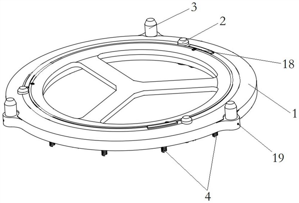
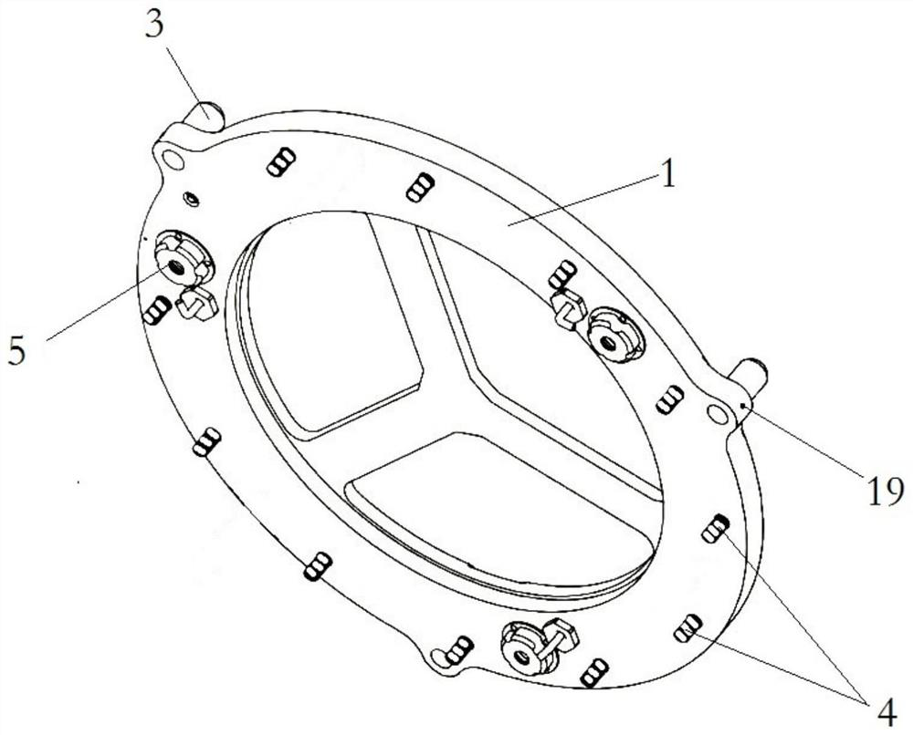
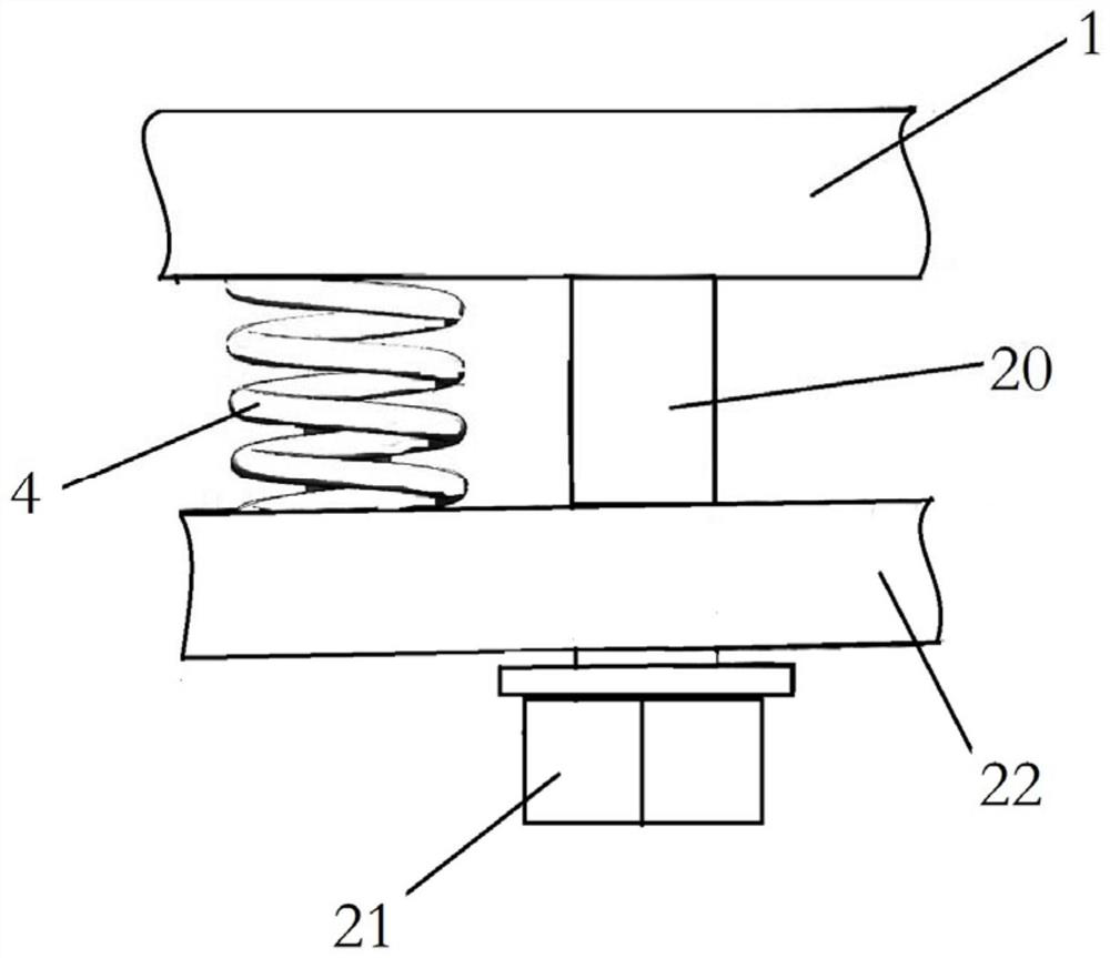
The invention provides a bearing platform with a wafer positioning function, and belongs to the technical field of semiconductors. The bearing platform comprises a substrate, the front surface of thesubstrate is provided with a clamping platform for supporting wafers, the periphery of the clamping platform is uniformly provided with a plurality of wafer positioning columns, polishing head positioning columns for positioning a polishing head are also arranged at the positions, on the outer sides of the wafer positioning columns, on the substrate, the bottom face of the substrate is suitable for being connected with a driving device through bolts, and the substrate is suitable for being elastically connected with the driving end of the driving device in an up-down sliding mode through the bolts. According to the bearing platform with the wafer positioning function, the wafer positioning precision is accurate, only one driving device is needed, and the reliability of the wafers in the loading and unloading process is improved.

Description

technical field [0001] The invention relates to the technical field of semiconductors, in particular to a carrying platform with a wafer positioning function. Background technique [0002] With the rapid development of integrated circuit manufacturing technology, IC chips continue to develop towards miniaturization and multi-layer interconnection. Chemical mechanical polishing technology has become the core technology of integrated circuit manufacturing. Chemical mechanical polishing equipment is mainly used in chemical mechanical polishing technology. Round surfaces are flattened. [0003] As the core component of chemical mechanical polishing equipment, the reliability of wafer loading and unloading device directly determines the long-term stable operation of chemical mechanical polishing equipment; [0004] Among them, the carrier in the wafer loading and unloading device is an auxiliary tool in wafer transfer. The specific process is: firstly, the wafer is moved from th...

Claims


Application Information

Patent Timeline
IPC IPC(8): B24B37/30B24B37/34B24B41/00B24B37/005B24B49/16H01L21/68H01L21/687
CPCB24B37/30B24B37/345B24B41/007B24B37/005B24B49/16H01L21/68H01L21/68785
Inventor 王鹏李伟费玖海尹影
Owner 北京晶亦精微科技股份有限公司
Why Eureka
Try Eureka