
Hydraulic lifting support machining production line for cable breaking

A hydraulic lifting and production line technology, applied in the direction of grinding workpiece supports, metal processing equipment, manufacturing tools, etc., can solve the problems of inconvenient measurement, inconvenient welding for operators, inconvenient welding of intermediate rods, etc.

Active Publication Date: 2020-10-23
HAIYAN AIHUA MACHINERY CO LTD
View PDF7 Cites 0 Cited by
  • Summary
  • Abstract
  • Description
  • Claims
  • Application Information

AI Technical Summary

Problems solved by technology

[0003] The most commonly used brackets are H-shaped, and there is a sliding frame connected between the H-shaped brackets. The hydraulic rod is installed on the middle rod of the H-shaped bracket, and the hydraulic rod drives the sliding frame to slide between the H-shaped brackets to complete the lifting purpose, while the H The most commonly used production method of the shaped bracket is welding. The two ends of the middle rod are welded with the H bracket. If the two ends of the middle rod are welded on the ground, it is inconvenient for the operator to weld at this time, and it is not convenient to carry out the welding on the four sides of the middle rod. Welding, and it is not convenient to measure before and after welding

Method used


Image

  • Hydraulic lifting support machining production line for cable breaking
  • Hydraulic lifting support machining production line for cable breaking
  • Hydraulic lifting support machining production line for cable breaking

Examples


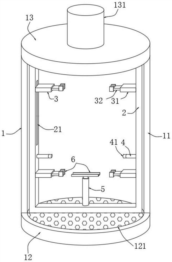
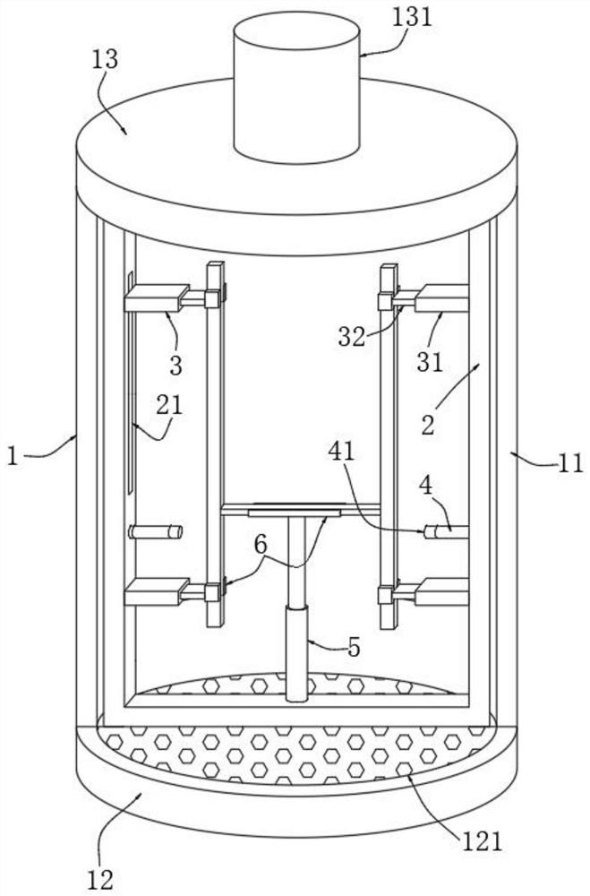
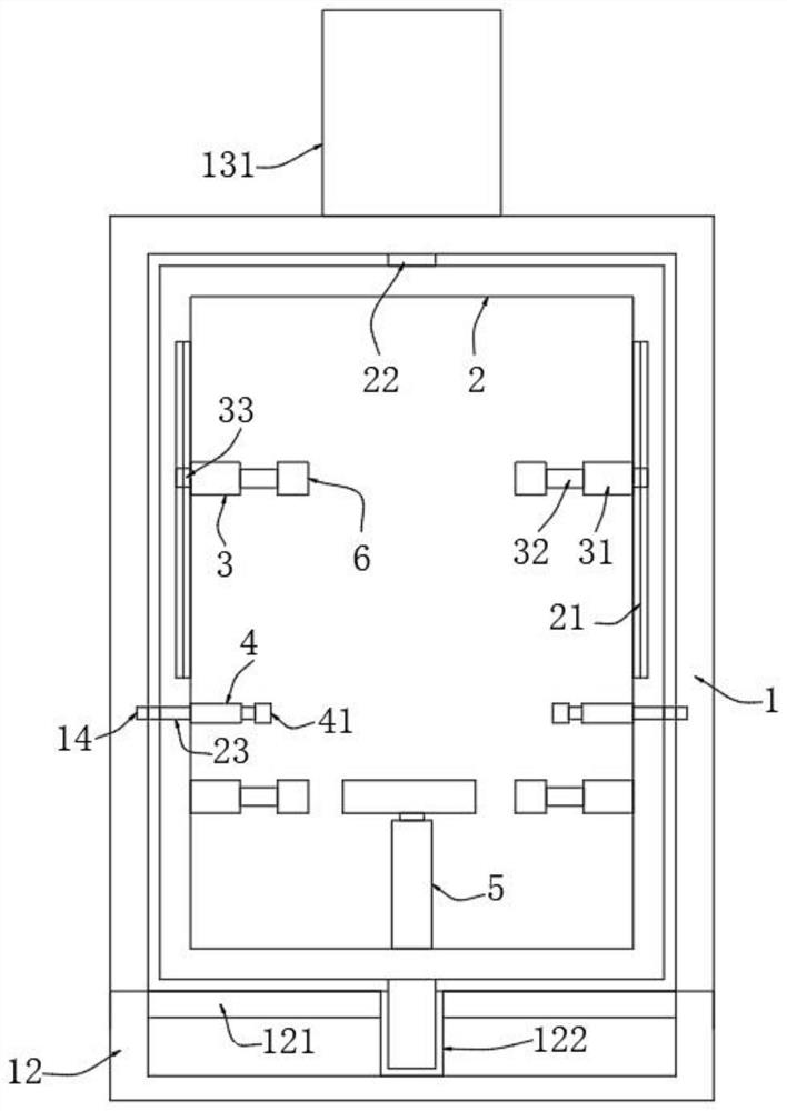
Embodiment Construction

[0027] The following will clearly and completely describe the technical solutions in the embodiments of the present invention with reference to the accompanying drawings in the embodiments of the present invention. Obviously, the described embodiments are only some, not all, embodiments of the present invention. Based on the embodiments of the present invention, all other embodiments obtained by persons of ordinary skill in the art without making creative efforts belong to the protection scope of the present invention.

[0028] see Figure 1-7 , the present invention provides the following technical solutions: a production line for processing hydraulic lifting supports for cable cutting, including a processing round bin 1, an open end 11 is provided on one side of the processing round bin 1, a top plate 13 is provided at the upper end of the processing round bin 1, and a processing round bin 1 is provided. 1 has a chassis 12 at the bottom end, and the inside of the processing ...


PUM


Abstract

The invention belongs to the technical field of frame processing, and particularly relates to a hydraulic lifting support machining production line for cable breaking. The production line comprises amachining circular bin, wherein four symmetrically distributed side positioning rods are arranged on the inner wall of a clamping frame, a bottom supporting rod is mounted on the bottom surface of theinner wall of the clamping frame, one ends of the side positioning rods and the bottom supporting rod are fixedly connected to bracket clamps, the bracket clamp comprises a fixed L plate and a sliding L plate slidably connected to one side of the fixed L plate, and the bracket clamp shapes like a Chinese character 'fang'. Sliding rods slide outward from fixing rods, two side rods move towards a middle rod, the middle rod is driven to rise upwards through the bottom supporting rod, then the fixed position between the middle rod and the side positioning rods is adjusted, a vertical H-shape is formed by the side rods and the middle rod at this time, an operator performs measurement welding between the middle rod and the side rods, the area occupation caused by the laying of a support is reduced, and the convenience of welding and measurement is improved.

Description

technical field [0001] The invention belongs to the technical field of frame processing, and in particular relates to a processing production line for hydraulic lifting supports for cable cutting. Background technique [0002] Cable is a general term for items such as optical cables and cables. There are many uses of cables, mainly used for multiple functions such as control installation, connection equipment, and power transmission. It is a common and indispensable thing in daily life. When cables are processed, they need to be cut off. Two kinds of hydraulic lifting brackets will be used. One bracket is used to support the cable roller and drive the cable roller to rise and fall, so as to meet the needs of different diameter cable rollers for rotating and feeding. The second is to drive the cutting through the hydraulic lifting bracket. The lifting of the mechanism completes the bracket used for cable cutting and material breaking. [0003] The most commonly used bracket...

Claims


Application Information

Patent Timeline
Patent Type & Authority Applications(China)
IPC IPC(8): B23K37/04B24B41/06
CPCB23K37/04B24B41/06
Inventor 金严斌金爱玉
Owner HAIYAN AIHUA MACHINERY CO LTD
Learn More