Special welding machine system for rapid metal forming through electric arc method and control method of special welding machine system

A metal rapid prototyping and arc method technology, applied in arc welding equipment, metal processing equipment, manufacturing tools, etc., can solve problems such as the inability to eliminate thermal stress

Pending Publication Date: 2020-10-23
江苏军智增材航空科技有限公司
View PDF2 Cites 1 Cited by
  • Summary
  • Abstract
  • Description
  • Claims
  • Application Information

AI Technical Summary

Problems solved by technology

However, the temperature control method of the molding substrate used in this technical solution is actually difficult to solve the thermal stress problem mentioned above. This method can at most eliminate a certain amount of thermal stress on the printing line segment in one direction. For 3...

Method used


Image

  • Special welding machine system for rapid metal forming through electric arc method and control method of special welding machine system
  • Special welding machine system for rapid metal forming through electric arc method and control method of special welding machine system
  • Special welding machine system for rapid metal forming through electric arc method and control method of special welding machine system

Examples


Embodiment 1

[0057] Such as figure 1 , figure 2 As shown, the special welding machine system used in this embodiment for arc metal rapid prototyping includes a controller and a frame 01, and the controller is communicated with an external computer; it also includes an arc power supply 02, a wire feeding assembly 03, and a voltage comparison device 04; the wire feeding assembly 03 is provided with a metal wire 05, and the controlled end of the wire feeding assembly 03 is connected to the control end of the controller; the frame 01 is provided with a three-dimensional motion device 06, and the controlled end of the three-dimensional motion device 06 is connected to the The control end of the controller is connected; the three-dimensional motion device 06 is respectively equipped with a welding torch head 07 connected with the wire feeding assembly 03 and a welding bottom plate 08, and the metal wire 05 penetrates the welding torch head 07; the welding torch head 07 and the welding bottom pl...

Embodiment 2

[0070] The welding machine system control method of the present embodiment adopts the special welding machine system used for the rapid metal arc prototyping in embodiment 1; as Figure 7 As shown, the control method of this embodiment includes:

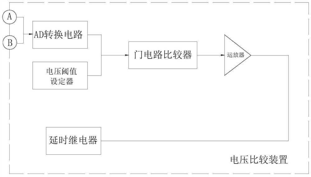
[0071] The first step is to start the welding machine system; the arc power supply 02 supplies electricity to the metal wire 05 through the welding torch head 07, and supplies electricity to the welding bottom plate 08 at the same time; the voltage comparison device 04 passes its first voltage detection terminal A and second voltage detection terminal B Monitor the real-time voltage between the wire 05 and the welding base 08;

[0072] In the second step, the external computer models the printing target, slices the model layer by layer, and obtains motion control commands and wire feeding control commands based on the sliced ​​data and inputs them into the controller; the controller controls the 3D motion device according to the inpu...


PUM


Abstract

The invention relates to a special welding machine system for rapid metal forming through an electric arc method and a control method of the special welding machine system. The system comprises a controller, a rack, an electric arc power source, a wire feeding assembly and a voltage comparison device. A metal wire is arranged in the wire feeding assembly. A three-dimensional movement device is arranged on the rack. A welding gun head and a welding bottom plate which are connected with the wire feeding assembly are respectively arranged on the three-dimensional movement device. The metal wire penetrates into the welding gun head. The welding gun head and the welding bottom plate are electrically connected with the electric arc power source. The voltage comparison device is provided with a first voltage detection end, a second voltage detection end and a delay switch. The first voltage detection end is electrically connected with the welding gun head. The second voltage detection end iselectrically connected with the welding bottom plate. The delay switch is connected into a connecting line of the welding gun head and the electric arc power source in series or connected into a connecting line of the welding bottom plate and the electric arc power source in series. The system is adopted in the control method. According to the special welding machine system for rapid metal formingthrough the electric arc method and the control method of the special welding machine system, transient short-circuit time is controlled through the voltage comparison device, heat accumulation is reduced, and the problem of thermal stress is avoided.

Description

technical field [0001] The invention relates to a special welding machine system for metal rapid prototyping by arc method and a control method thereof, belonging to the technical field of rapid metal printing and prototyping. Background technique [0002] As far as the applicant knows, metal rapid printing and prototyping technology is a digital manufacturing technology that uses high-energy beams as a heat source and accumulates materials layer by layer to realize moldless forming of components. The principle of rapid printing and forming of metal parts is to melt and accumulate metal powder or wire under heating conditions such as electric arc, laser or electron beam, according to the path set by the software, and finally form the designed part entity. [0003] The proportion of the application of large and complex key structural parts in the world's manufacturing industry has become an important technical indicator to measure the advancement of major equipment such as mi...

Claims


Application Information

Patent Timeline
IPC IPC(8): B23K9/04B23K9/067B23K9/10B23K9/133B23K9/32
CPCB23K9/10B23K9/133B23K9/32B23K9/067B23K9/04
Inventor 傅强王健
Owner 江苏军智增材航空科技有限公司
Why Eureka
Try Eureka