Correcting device for machining thin-wall cylinder parts

A technology for parts processing and thin-walled cylinders, applied in the field of calibration devices, can solve problems such as inability to process and flanging of sidewall holes of cylinder-type parts.

Active Publication Date: 2020-10-23
东莞市鸿凯精密科技有限公司
View PDF8 Cites 2 Cited by
  • Summary
  • Abstract
  • Description
  • Claims
  • Application Information

AI Technical Summary

Problems solved by technology

However, for the flanging of the side wall hole of thin-walled cylindrical parts, the flanging direction is along the radial direction of the part cylinder, and the concave and convex die processing also needs to apply punching force to the radial direction of the part cylinder, but due to the rotation of the part itself characteristics, the cylinder wall will interfere with the configuration of the concave and convex molds, making it impossible to process
In this way, the conventional concave-convex die design cannot flang the side wall holes of cylindrical parts

Method used


Image

  • Correcting device for machining thin-wall cylinder parts
  • Correcting device for machining thin-wall cylinder parts
  • Correcting device for machining thin-wall cylinder parts

Examples


Embodiment Construction

[0055] In order to make the purpose, technical solutions and advantages of the present invention clearer, the present invention will be further described in detail below in conjunction with the examples and accompanying drawings. As a limitation of the present invention.

[0056] As indicated in this application and claims, the terms "a", "an", "an" and / or "the" do not refer to the singular and include the plural unless the context clearly indicates an exception.

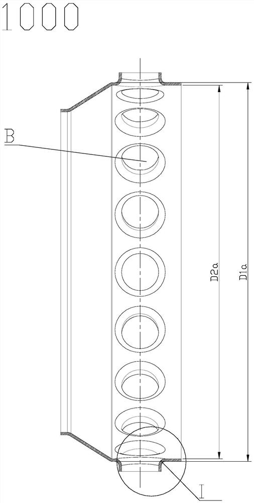
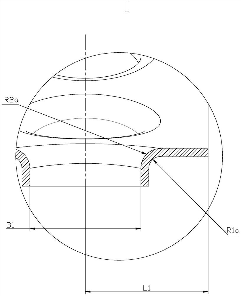
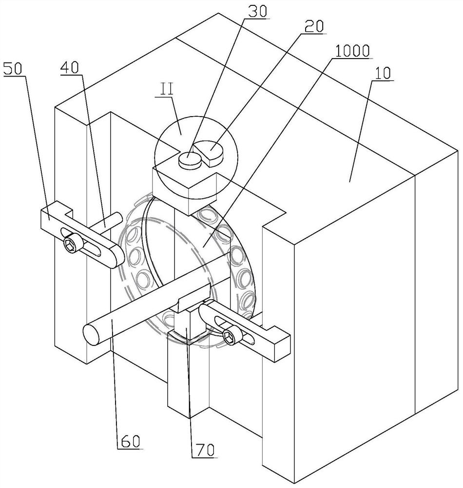
[0057] In some embodiments, such as image 3 The calibrating device shown is used for processing and calibrating the flanging hole of the side wall of a thin-walled cylindrical part, for example, calibrating the flanged cylinder B of the part 1000. Parts 1000 as figure 1 and figure 2 Shown is a cylindrical thin-walled part, and a flanging convex cylinder B that flangs outward is arranged on the outer ring surface D1a. The dimensions that need to be guaranteed for the flanging boss B include the diameter of the ...


PUM


Abstract

The invention discloses a correcting device for machining thin-wall cylinder parts. The correcting device is characterized in that a hinged pressing rod is arranged in a base body, a punching part forapplying punching pressure is arranged on the pressing rod, and a punch and a first positioning block are arranged to be used as a female die and a male die respectively. When in use, the parts to bemachined are placed on the first positioning block, the outer ring surfaces of the parts to be machined are attached to the outer ring matching surface of the first positioning block, then the punchis sequentially inserted into flanging inner holes of the parts and a forming hole of the first positioning block, and then the operating end of the pressing rod is held with hands, so that the pressing rod hits the top surface of the punch through rotary motion, component force in the flanging direction of flanging convex cylinders is generated, consequently, the forming part on the punch is matched with the forming hole to exert pressure on the inner surfaces and the outer surfaces of the parts, then the parts are subjected to plastic deformation for flanging, and thus the machining requirement is met.

Description

technical field [0001] The invention relates to the field of mechanical processing equipment, in particular to a calibration device for processing thin-walled cylindrical parts. Background technique [0002] Flanging is a common form in the stamping process. Through the mutual cooperation of the punch and die, the sheet metal parts to be processed are plastically deformed at specific positions, and thus are bent into various shapes. [0003] The flanging calibration of the side wall holes of thin-walled cylindrical parts is to recalibrate the size of the flanging convex cylinder if the cylindrical parts do not meet the use requirements during long-term use or processing, so that they can meet the use requirements again. need. However, for the flanging of the side wall hole of thin-walled cylindrical parts, the flanging direction is along the radial direction of the part cylinder, and the concave and convex die processing also needs to apply punching force to the radial dire...

Claims


Application Information

Patent Timeline
IPC IPC(8): B21D3/16
CPCB21D3/16
Inventor 孙君
Owner 东莞市鸿凯精密科技有限公司
Why Eureka
Try Eureka