
Method for filling aerosol generating product and aerosol generating product prepared thereby

An aerosol generation and product technology, which is applied in the manufacture of cigarettes, cigars, smoke oil filters, etc., can solve the problems of pipe pollution, material waste, and large loss of raw materials

Pending Publication Date: 2020-10-23
YUNNAN XIKE TECH CO LTD
View PDF4 Cites 8 Cited by
  • Summary
  • Abstract
  • Description
  • Claims
  • Application Information

AI Technical Summary

Problems solved by technology

That is to say, the sealing of the aerosol generating product in the prior art is at the far lip end, and the smoke particles are filled from the end of the pipe near the lip end. After the pipe is sealed, it needs to be filled from the near lip end of the pipe. The smoking material is loaded into the far lip end of the pipe, and the pipe is easily polluted by the moisture of the smoking particles or the smoking paste, the smoking agent, the fragrance material, and the color of the particle itself, which mainly leads to three problems: 1. 1. Severe waste of materials, large loss of raw materials, and low pass rate; 2. High intensity and low efficiency of manual quality inspection; 3. Affecting consumers' smoking experience

Method used


Image

  • Method for filling aerosol generating product and aerosol generating product prepared thereby
  • Method for filling aerosol generating product and aerosol generating product prepared thereby
  • Method for filling aerosol generating product and aerosol generating product prepared thereby

Examples


Embodiment 1

[0045] This example is the preparation of sample 1 of the aerosol generating product.

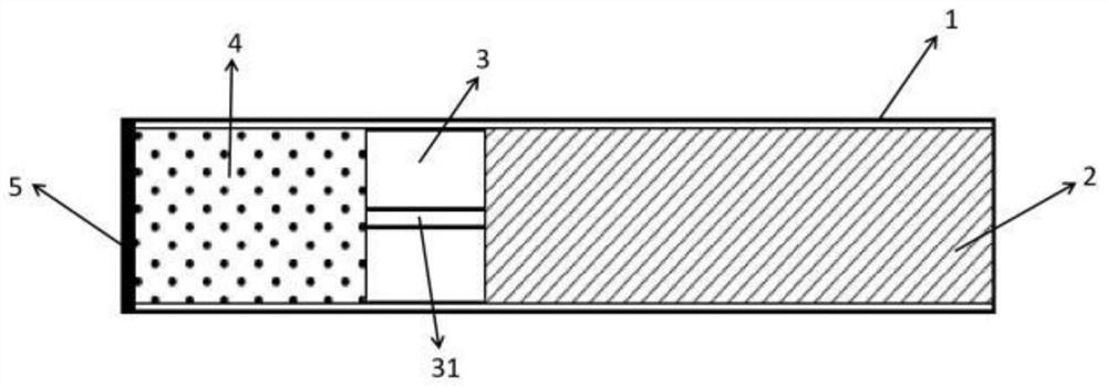
[0046] Such as figure 1 , the aerosol generating product sample 1 includes a tube body 1, a filter component 2 arranged in sequence from the proximal lip end to the distal lip end in the tube body 1, a blocking flow guide component 3, a smoke unit 4, and a tube body 1 located on the far lip The sealing member 5 of the end face.

[0047] The filling method of aerosol generating product sample 1 comprises the following steps ( Figure 6 ): (1) prepare the tube body 1 of the aerosol generating product; (2) fill the filter component 2 in the tube body 1, and the filter component 2 is close to the near-lip end surface of the tube body 1; (3) Install the barrier flow guide part 3 from the far lip end of the tube body 1, and the barrier flow guide part 3 is close to the filter part 2; (4) install the smoking unit 4 from the far lip end of the tube body 1, so that The smoking unit 4 is located ...

Embodiment 2

[0050] This example is the preparation of sample 2 of the aerosol generating product.

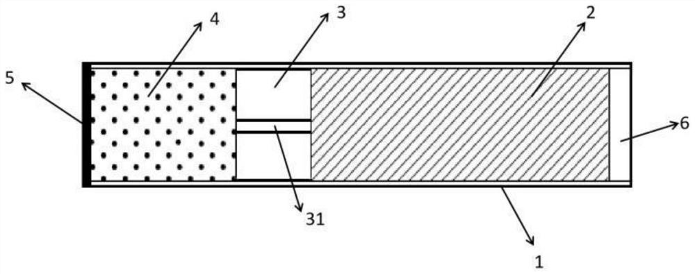
[0051] Such as figure 2 , the aerosol generating product sample 2 includes a tube body 1, a settling unit 6, a filter component 2, a barrier flow guide component 3, a smoke unit 4, and a settling unit located in the tube body 1 arranged in sequence from the near lip end to the far lip end, and the The sealing member 5 on the end face of the far lip end of the body 1.

[0052] The filling method of the sample 2 of the aerosol generating product comprises the following steps: (1) preparing the tube body 1 of the aerosol generating product; (2) filling the filter part 2 in the tube body 1, and the filter part 2 is close to the tube The near lip end of the body 1; a certain cavity is left between the filter part 2 and the near lip end face of the tube body 1, and this cavity is the settling unit 6; (3) from the tube body 1 The far lip end is loaded into the blocking and guiding part 3, and t...

Embodiment 3

[0055] This example is the preparation of sample 3 of the aerosol generating product.

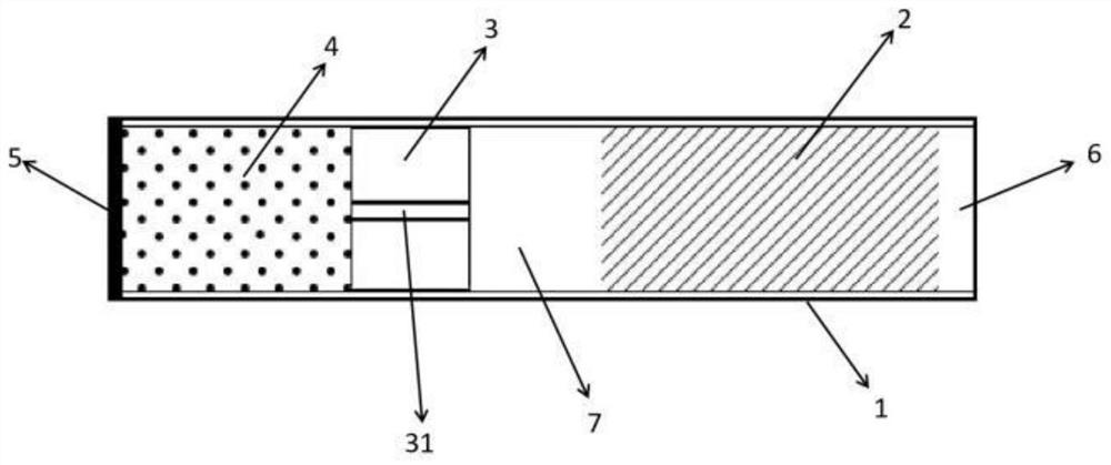
[0056] Such as image 3 The aerosol generating product sample 3 includes a tube body 1, a settling unit 6, a filter component 2, a functional unit 7 in the form of a cavity, a barrier flow guiding component 3, The smoking unit 4, and the sealing member 5 located on the end surface of the distal lip end of the tube body 1.

[0057] The filling method of the aerosol generating product sample 3 comprises the following steps: (1) preparing the tube body 1 of the aerosol generating product; (2) filling the filter part 2 in the tube body 1, and the filter part 2 is close to the tube Near the lip end of the body 1, there is a certain cavity between the filter part 2 and the near lip end face of the tube body 1, and this cavity is the settling unit 6; (3) from the tube body 1 The far lip end is packed into the blocking flow guiding part 3, but there is a section of cavity between the blocking flo...


PUM


Abstract

The invention discloses a method for filling an aerosol generating product. The method comprises the following steps of (1) preparing a tube body (1) of the aerosol generating product, (2) filling a filtering part (2) in the tube body (1), wherein the filtering part (2) is close to the near lip end of the tube body (1), (3) installing the blocking flow guide part (3) from the far lip end of the tube body (1), (4) installing a fuming unit (4) from the far lip end of the tube body (1), wherein the smoke generating unit (4) is positioned at the far lip end of the tube body (1), and (5) sealing the far lip end of the tube body (1), and forming a sealing piece (5) on the end surface of the far lip end of the tube body (1). Each part is sequentially filled from the near lip end to the far lip end of the aerosol generating product for the first time, so that the pollution to the tube body (1) caused by the fuming unit (4) when the fuming unit (4) is filled is effectively avoided, the appearance qualification rate of the product can reach 100%, the manual quality inspection strength is reduced, the efficiency is improved, the loss is reduced, and the profit margin is increased for enterprises.

Description

technical field [0001] The patent of the present invention relates to the technical field of low-temperature heat-not-burn products production, in particular to a method for filling an aerosol generating product and the prepared aerosol generating product. Background technique [0002] Low-temperature heating-not-burning products have been highly praised by many tobacco companies due to the low-temperature heating-not-burning products, which greatly reduce the harmful substances in the smoke, and have less second-hand smoke. At present, the smoking sections of low-temperature heat-not-burn products on the market mainly include particle type, shredded tobacco or sheet type, and paste-like smoking materials. [0003] CN 110292196A patent discloses a pod production line, which includes a paper tube unloading mechanism, a paper tube sticking paper mechanism, a smoke particle unloading mechanism, a firmware unloading mechanism, a filter particle unloading mechanism, a bead unload...

Claims


Application Information

Patent Timeline
IPC IPC(8): A24D1/20A24D1/04A24D3/17A24C5/01
CPCA24D1/20A24D1/042A24D3/17A24C5/01A24C5/02A24C5/18A24D3/0229A24D3/0262A24C5/1807A24D3/025A24C5/1885A24D1/02A24D1/045A24D1/14A24D3/10A24D3/063A24D3/0279A24D3/0216A24D3/048A24F40/70A24F40/42A24C5/47
Inventor 燕宁宁张勇黄振楠陈岳锋袁盛洪张强王松峰陈征
Owner YUNNAN XIKE TECH CO LTD
Learn More