Solar efficient power generation device

A power generation device and solar technology, applied in the field of solar power generation, can solve the problems of short power generation time, monotonous functions, and large silicon battery consumption

Pending Publication Date: 2020-10-20
沙旭崎
View PDF0 Cites 0 Cited by
  • Summary
  • Abstract
  • Description
  • Claims
  • Application Information

AI Technical Summary

Problems solved by technology

[0009] The purpose of the present invention is to solve the existing problems of existing solar power generation devices, which occupy a large area, consume a large number of silicon cells, have high cost, and low power generation efficiency. Pollution such as accumulated dust or snow will cause the light transmittance of photovoltaic panels to decrease, and the surface will corrode, resulting in reduced power generation efficiency, shortened life span, and even damage, which will affect the appearance of the building and lighting requirements. It can only be used for power generation, with monotonous functions and aesthetics. The specific solutions to the problem of insufficient practicability are as follows:

Method used


Image

  • Solar efficient power generation device
  • Solar efficient power generation device
  • Solar efficient power generation device

Examples


Embodiment 1

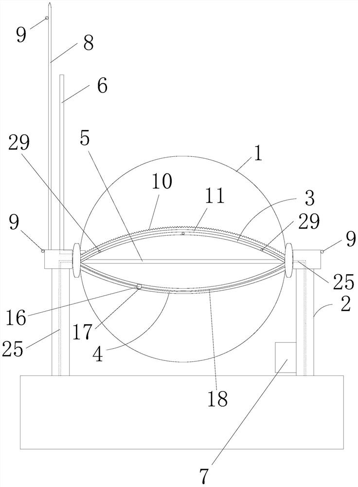
[0043] like figure 1 , 2As shown in the figure, a high-efficiency solar power generation device includes a glass spherical shell 1, which is sealed with a transparent liquid (not shown in the figure) filled inside the glass spherical shell 1. At both ends of the glass spherical shell 1 along the horizontal diameter, there are The fixing bracket 2, around the outer surface of the glass spherical shell 1, is provided with a first semicircular track 3, the two ends of the first semicircular track 3 are respectively connected with the fixing bracket 2 in rotation, and along the outer side of the first semicircular track 3, there is a second semicircular track 3. The two ends of the semicircular track 4 and the second semicircular track 4 are respectively rotatably connected with the fixing bracket 2 . From one fulcrum end of the fixed bracket 2, there is a transparent L-shaped sealed communication connector 6 that communicates with the interior of the glass spherical shell 1. The...

Embodiment 2

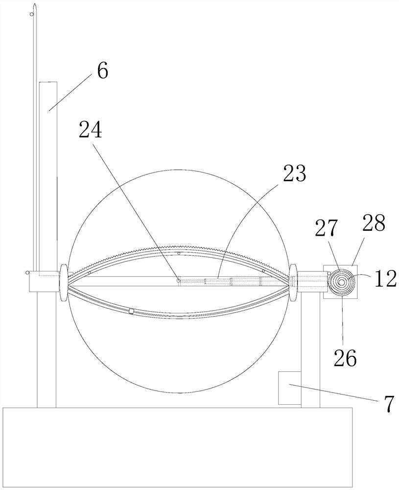
[0053] like image 3 , 4 As shown, the difference from the above-mentioned Embodiment 1 is that this embodiment is provided with an automatic telescopic rod 23 from the other end of the fulcrum of the fixed bracket 2 to the inside of the glass spherical shell 1, and the front end of the automatic telescopic rod 23 is provided. There is an LED light 24, the entrance of the automatic telescopic rod 23 is a sealed structure, the joints between each sleeve 32 of the automatic telescopic rod 23 are respectively provided with sealing rings 33, and the tail end of the automatic telescopic rod 23 is The second rotary motor 26 is connected, the second rotary motor 26 is mounted on the bracket 28 outside the fixed bracket 2 , and the second rotary motor 26 is electrically connected to the controller box 7 . During the day, the automatic telescopic rod 23 is hidden in the end of the fixed bracket 2. The automatic telescopic rod 23 is sleeved by a plurality of sleeves 32 (its structure i...

Embodiment 3

[0055] like Figure 5 As shown, the difference from the above-mentioned Embodiment 1 is that the shape of the fixing bracket 2 in this embodiment is a horseshoe shape. The rest of the content is exactly the same as that in Embodiment 1, and will not be repeated here.


PUM


Abstract

The invention discloses a solar efficient power generation device. The device comprises a spherical glass shell, and transparent liquid filled in the glass spherical shell in a sealed manner. On two ends of the glass spherical shell along the horizontal diameter, a fixing support is arranged. A first semicircular track is arranged around the outer surface of the glass spherical shell. Along the outer side of the first semi-circular rail, a second semi-circular rail is arranged. From one fulcrum end of the fixing support, an L-shaped sealing communicating vessel communicated with the interior of a glass spherical shell is arranged. A water spraying type washing and scraping mechanism is arranged on a first semi-circular rail. A tracking type photosensitive mechanism and a photosensitive plate cleaning mechanism are arranged on a second semicircular track. A controller box is arranged on one side of a fixing support, and a single-chip microcomputer chip, a photoelectric conversion moduleand a storage battery are arranged in the controller box. The scheme has the advantages of small size, automatic sun tracking, intelligent analysis, automatic cleaning, long power generation time, high power generation efficiency and wide application range.

Description

technical field [0001] The invention relates to the field of solar power generation, in particular to a solar energy high-efficiency power generation device. Background technique [0002] Although photovoltaic power generation (that is, solar power generation) technology has already matured, it still cannot reach the level of universal use. The reason is that the existing solar power generation devices have the following defects: [0003] (1) It occupies a large area, consumes a lot of silicon cells, has high cost and low power generation efficiency. [0004] (2) Photovoltaic panels (that is, solar panels) do not track the movement of the sun, and their power generation time is short. [0005] (3) The power generation devices are all arranged in the open air, facing pollution such as dust or snow, which causes the decrease of light transmittance and surface corrosion of photovoltaic panels, resulting in reduced power generation efficiency, shortened lifespan and even damage...

Claims


Application Information

Patent Timeline
IPC IPC(8): H02S10/00H02S20/32H02S40/10H02S40/12H02S40/22H02S40/30F21V33/00F21Y115/10
CPCH02S50/00H02S40/10H02S40/30H02S50/10Y02E10/52
Inventor 沙旭崎
Owner 沙旭崎
Why Eureka
Try Eureka