Hydraulically driven low-temperature reciprocating pump capable of reducing influence of low temperature on piston rod seal

A piston rod and reciprocating pump technology, applied in the field of hydraulically driven low-temperature reciprocating pumps, can solve problems such as seal failure, hydraulic oil leakage, and temperature reduction of the piston rod surface, and achieve the effects of ensuring the life of the seal, preventing frosting, and reducing friction

Pending Publication Date: 2020-10-20
HUZHOU SANJING CRYOGENIC EQUIP
View PDF0 Cites 0 Cited by
  • Summary
  • Abstract
  • Description
  • Claims
  • Application Information

AI Technical Summary

Problems solved by technology

[0004] The hydraulically driven cryogenic reciprocating pump, the driving end is connected to the storage tank of the cryogenic pump, and the piston rod at the driving end is generally sealed with an oil seal. Because the piston rod at the driving end will be affected by the low temperature of the low temperature medium, the surface temperature of the piston rod at the driving end will drop. , As a result, the seal of the oil seal is affected by the low temperature, the elasticity of the polyurethane or rubber oil seal is reduced, the entire oil seal becomes hard and brittle, and the seal fails, resulting in leakage of hydraulic oil
Existing hydraulically driven low-temperature reciprocating pumps increase the temperature area by lengthening the piston rod length, but due to the increase in the volume of the piston rod, the hydraulic power remains unchanged, which will reduce the frequency of piston rod activity, and the seal will still be subject to a certain low temperature. There is also electric heating to solve the influence of connecting rod surface temperature, but the structure of electric heating is more complicated

Method used


Image

  • Hydraulically driven low-temperature reciprocating pump capable of reducing influence of low temperature on piston rod seal
  • Hydraulically driven low-temperature reciprocating pump capable of reducing influence of low temperature on piston rod seal

Examples


Embodiment Construction

[0018] specific implementation plan

[0019] The following will clearly and completely describe the technical solutions in the embodiments of the present invention with reference to the accompanying drawings in the embodiments of the present invention. Obviously, the described embodiments are only some, not all, embodiments of the present invention.

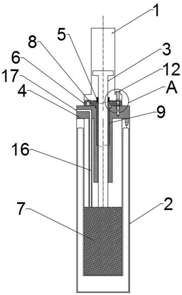
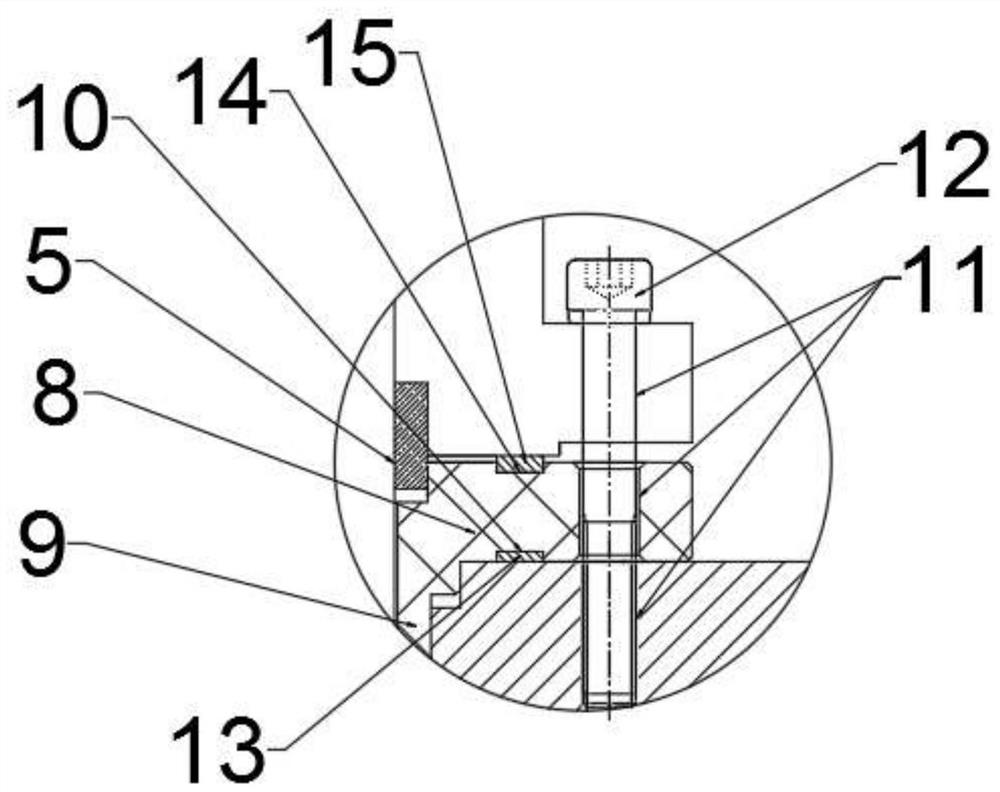
[0020] refer to figure 1 , the present invention provides a technical solution: a hydraulically driven low-temperature reciprocating pump that can reduce the impact of low temperature on the seal of the piston rod, including a cylinder body 1, a pump body 2 and a piston rod 3, and the pump body 2 includes a vacuum storage tank 7 and a pump The body end cover 4 and the vacuum storage tank 7 are equipped with cryogenic media with extremely low temperature, such as liquid nitrogen or liquid methane and other media; the opening of the pump body 2 is provided with a pump body end cover 4; the pump body end cover 4 is fixedly connected...


PUM


Abstract

The invention discloses a hydraulically driven low-temperature reciprocating pump capable of reducing influence of low temperature on a piston rod seal. The hydraulically driven low-temperature reciprocating pump comprises a cylinder body, a pump body and a piston rod, wherein the pump body is internally provided with a low-temperature medium storage tank, and an opening of the pump body is provided with an end cover fixedly connected with the pump body; the cylinder body is arranged above the pump body; one end of the piston rod penetrates through the end cover and extends to a cylinder bodycavity, and reciprocates in the cylinder body cavity; the piston rod is provided with a rubber sealing ring for oil sealing; and a heat-insulating and radiation-proof protective sleeve is provided between the cylinder body and the end cover. The hydraulically driven low-temperature reciprocating pump capable of reducing the influence of the low temperature on the piston rod seal provided by the invention has many advantages such as ensuring the sealing life of the rubber sealing ring, preventing frosting at the opening of the pump body, and reducing the friction between the piston rod and thecavity.

Description

technical field [0001] The invention relates to the field of hydraulically driven low-temperature reciprocating pumps, in particular to a hydraulically driven low-temperature reciprocating pump capable of reducing the impact of low temperature on the piston rod seal. Background technique [0002] The hydraulically driven reciprocating pump has a wide range of uses. Compared with the traditional reciprocating pump, the crank linkage mechanism is removed, and the hydraulic cylinder is used for driving and hydraulic control. It can have long strokes and low stroke times, which greatly improves the working performance. However, hydraulically driven reciprocating pumps also require a piston rod that reciprocates axially in the pump working chamber. [0003] The hydraulically driven reciprocating pumps described above have particular application in those cryogenic pumps involving extremely high pressures. For example, cryopumps for media such as liquid nitrogen or liquid methane ...

Claims


Application Information

Patent Timeline
Patent Type & Authority Applications(China)
IPC IPC(8): F04B37/08F04B39/06F04B39/00F04B35/00
CPCF04B35/00F04B37/08F04B39/00F04B39/0005F04B39/0022F04B39/06
Inventor 朱登凯汪国洪嵇伟峰李涛
Owner HUZHOU SANJING CRYOGENIC EQUIP
Why Eureka
Try Eureka