Rapid mounting device for medium and small sleeves of blast furnace tuyere

A technology for installing devices and tuyere, applied in the direction of tuyere, etc., can solve the problems of high production cost and maintenance cost, hidden safety hazards in operation, and inability to switch at will.

Pending Publication Date: 2020-10-20
DAYE SPECIAL STEEL CO LTD
View PDF0 Cites 0 Cited by
  • Summary
  • Abstract
  • Description
  • Claims
  • Application Information

AI Technical Summary

Problems solved by technology

[0004] 1) Using the traditional replacement device for the middle and small tuyeres, it is difficult to complete the transfer in one step during the replacement of the middle and small tuyeres, and the operation is often repeated many times, and the sealing surface of the middle and small tuyeres is easy to be damaged during the transfer process , high rework rate
[0005] 2) Using the traditional medium and small tuyere replacement devices, the front end needs to be manually positioned by someone. During the operation, it needs to be in close contact with high temperature and gas environment, which is easy to cause burns, and there are safety hazards in the operation
[0006] 3) Using the traditional replacement device for the middle and small sets of the tuyere, the installation of the middle set requires the use of chain hoists and other supporting tools. The installation is complicated and time-consuming, which virtually increases the labor intensity of the workers and greatly reduces the efficiency.
[0007] 4) Use the traditional medium and small tuyere replacement device, which occupies a large area and cannot be used when working in the narrow tuyere platform area of ​​some blast furnaces
[0008] 5) Use the traditional medium and small tuyere replacement device, which only has a single function, either only the small tuyere or the middle tuyere can be installed, and cannot be switched at will
[0009] 6) Using the traditional medium and small sets of tuyere replacement devices, the production cost and maintenance cost are relatively high

Method used


Image

  • Rapid mounting device for medium and small sleeves of blast furnace tuyere
  • Rapid mounting device for medium and small sleeves of blast furnace tuyere
  • Rapid mounting device for medium and small sleeves of blast furnace tuyere

Examples


Embodiment Construction

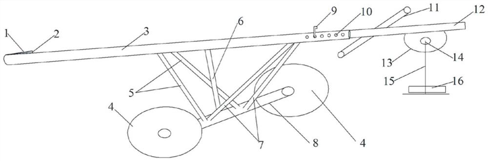
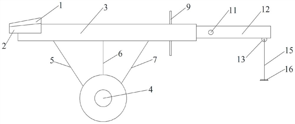
[0040] The technical solutions in the embodiments of the present invention will be clearly and completely described below, obviously, the described embodiments are only some of the embodiments of the present invention, not all of the embodiments. All other embodiments obtained by persons of ordinary skill in the art based on the embodiments of the present invention belong to the protection scope of the present invention.

[0041] In the description of the present invention, the terms "longitudinal", "transverse", "upper", "lower", "front", "rear", "left", "right", "vertical", "horizontal", " The orientations or positional relationships indicated by "top", "bottom", etc. are based on the orientations or positional relationships shown in the drawings, and are only for the convenience of describing the present invention and do not require that the present invention must be constructed and operated in a specific orientation, so they cannot be understood as Limitations on the Inven...


PUM


Abstract

The invention provides a rapid mounting device for medium and small sleeves of a blast furnace tuyere. The rapid mounting device comprises a moment arm unit, a protection unit, a moving unit and a counterweight unit, wherein the moment arm unit comprises a first moment arm and a second moment arm, one end of the second moment arm is nested into the first moment arm, the second moment arm performssliding motion in the axial direction relative to the first moment arm, the protection unit is arranged at one end of the moment arm unit, the moving unit is arranged on the ground, and the counterweight unit is arranged at the other end of the moment arm unit. In the operating process of the device, the relative position of the second moment arm can be adjusted, safety of an operator is guaranteed, parts of the units are mechanically connected through plug pins and the like, and mounting and maintenance are convenient; and the device is simple in structure, flexible to mount, low in manufacturing cost and convenient to operate, and during working, replacing time can be shortened, working efficiency is greatly improved, labor intensity is reduced, and conditions are created for reduction of the downtime ratio of a blast furnace.

Description

technical field [0001] The invention belongs to the technical field of iron and steel smelting, and in particular relates to a quick installation device for middle and small sets of blast furnace tuyeres. Background technique [0002] In blast furnace ironmaking production, it is often necessary to replace the tuyere cooling equipment (tuyere middle sleeve or tuyere small sleeve), the existing technology is to put the main breakthrough in the disassembly step of the replacement process, and try every means Shorten the time for dismantling the old tuyere cooling equipment to improve work efficiency, while the installation process of new equipment still requires manual operation to send it into the blast furnace tuyere in a high-temperature and gas-dangerous environment, and because the cooling equipment is heavy and the working space is small, The installation of new equipment is time-consuming and labor-intensive due to the inability of a single person to complete the positi...

Claims


Application Information

Patent Timeline
IPC IPC(8): C21B7/16
CPCC21B7/166
Inventor 李严张小毛岳争超熊伟刘田吴敦调刘登山
Owner DAYE SPECIAL STEEL CO LTD
Why Eureka
Try Eureka