Automatic cutting machine for silicone products
A cutting machine and product technology, applied in metal processing and other directions, can solve the problems of inaccurate cutting, low cutting efficiency, inability to realize automatic cutting function, etc., to achieve the effect of accurate cutting and providing cutting efficiency
- Summary
- Abstract
- Description
- Claims
- Application Information
AI Technical Summary
Problems solved by technology
Method used
Image
Examples
Embodiment 1
[0050] An automatic cutting machine for silicone products, such as figure 1 As shown, it includes a cutting frame 1, an intermittent drive mechanism 2, an intermittent transmission mechanism 3, a cutting mechanism 4, and a discharge tray 5. The upper part of the cutting frame 1 is equipped with an intermittent driving mechanism 2, and the middle part of the rear side of the cutting frame 1 An intermittent transmission mechanism 3 is installed, and the intermittent transmission mechanism 3 is located below the intermittent driving mechanism 2. A plurality of discharge trays 5 are evenly arranged on the intermittent transmission mechanism 3. The intermittent driving mechanism 2 cooperates with the intermittent transmission mechanism 3, and the cutting frame 1 and the intermittent A cutting mechanism 4 is installed between the driving mechanisms 2 , and the cutting mechanism 4 is located directly above the discharge tray 5 .
[0051] When it is necessary to cut the silicone produ...
Embodiment 2
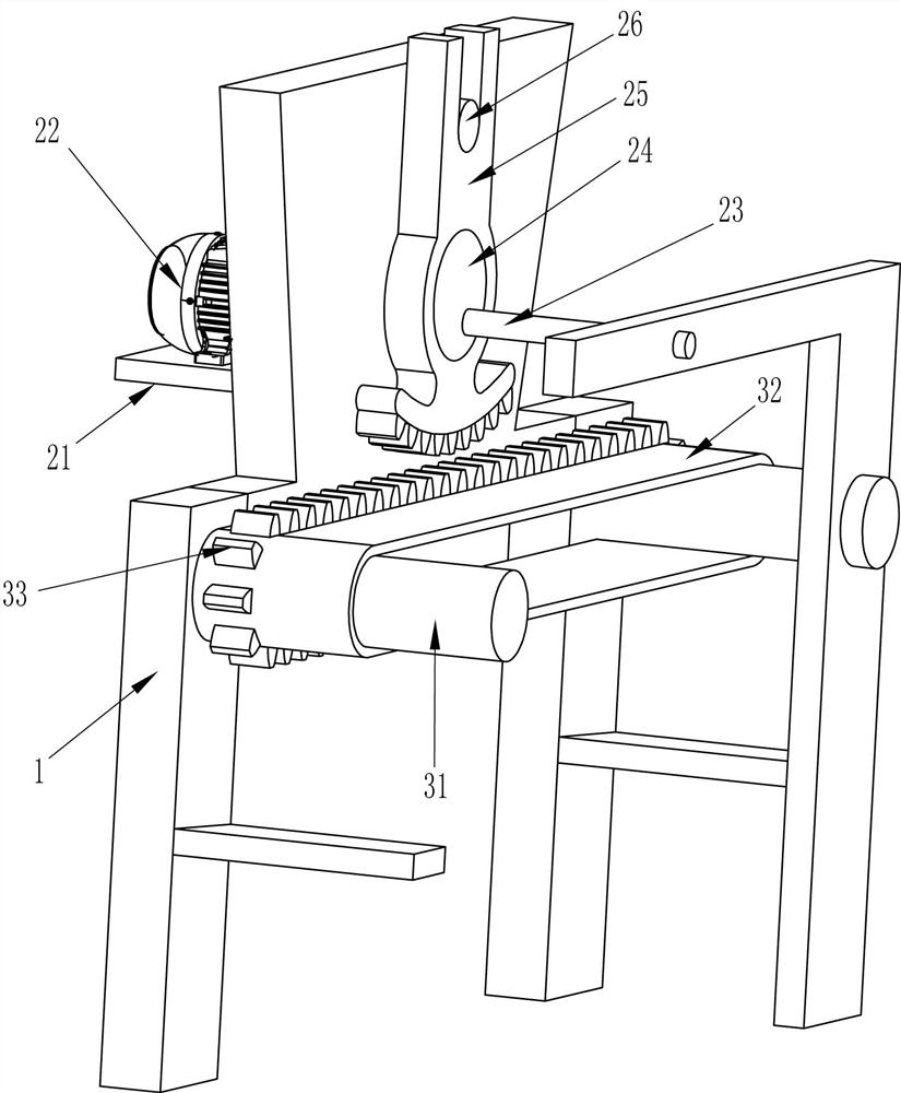
[0053] On the basis of Example 1, such as Figure 2-4 As shown, the intermittent drive mechanism 2 includes a mounting plate 21, a geared motor 22, a rotating rod 23, a runner 24, a sector gear 25 and a pole 26, and the upper part of the cutting frame 1 rear side is provided with a mounting plate 21, and on the mounting plate 21 Geared motor 22 is installed, and rotating link 23 is connected between cutting frame 1 front and rear both sides top, and rotating bar 23 rear sides are connected with the output shaft of geared motor 22, and the front wall top of cutting frame 1 rear side is provided with support. Rod 26, below the pole 26 is provided with a runner 24, the eccentric part of the runner 24 is connected with the rotating rod 23, a sector gear 25 is set between the pole 26 and the runner 24, the sector gear 25 and the intermittent transmission mechanism 3 Cooperate.
[0054] Intermittent transmission mechanism 3 comprises transmission shaft 31, conveyor belt 32 and toot...
Embodiment 3
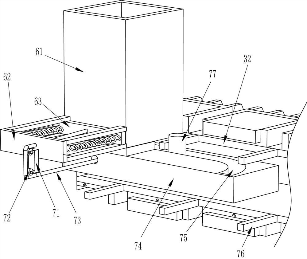
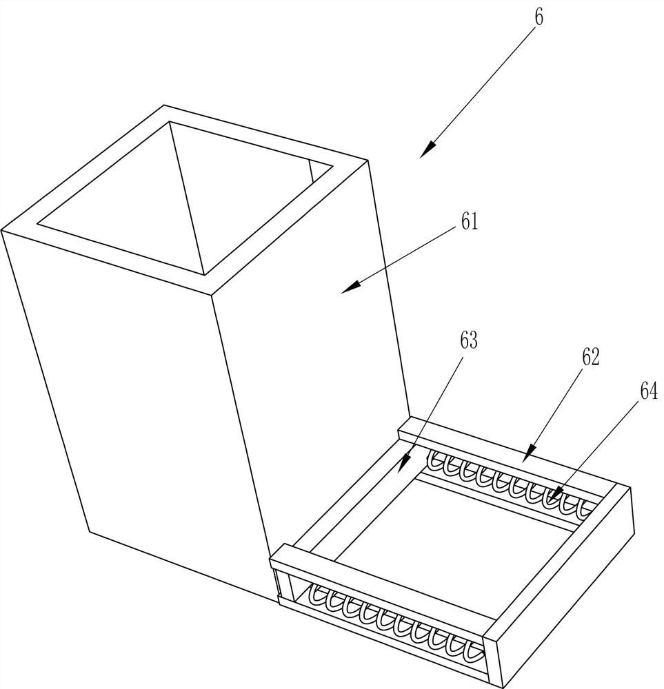
[0060] On the basis of Example 2, such as Figure 5-7 Shown, also include feeding mechanism 6, and feeding mechanism 6 includes placement frame 61, installation frame 62, pusher plate 63 and feed spring 64, and the front side left part of cutting frame 1 is provided with placement frame 61, The lower part of the rear side of the placing frame 61 has an opening, the front side of the placing frame 61 is connected with a mounting frame 62, and the sliding type is connected with a pushing plate 63 in the mounting frame 62, and the pushing plate 63 is positioned at the lower part of the placing frame 61 and cooperates with it. Feeding springs 64 are connected to the left and right parts of the front side of the material plate 63 , and the ends of the feeding springs 64 are connected to the front of the mounting frame 62 .
[0061] Also include feeding auxiliary mechanism 7, feeding auxiliary mechanism 7 includes fixed block 71, guide wheel 72, stay cord 73, fixed plate 74, push ro...
PUM
 Abstract
Description
Claims
Application Information
 - R&D
- Intellectual Property
- Life Sciences
- Materials
- Tech Scout
- Unparalleled Data Quality
- Higher Quality Content
- 60% Fewer Hallucinations
Browse by: Latest US Patents, China's latest patents, Technical Efficacy Thesaurus, Application Domain, Technology Topic, Popular Technical Reports.
© 2025 PatSnap. All rights reserved.Legal|Privacy policy|Modern Slavery Act Transparency Statement|Sitemap|About US| Contact US: help@patsnap.com


