Atomizer
An atomizer and atomizing tablet technology, which is applied in the field of atomizers and can solve the problems of odor, mixed-odor atomizer, liquid leakage, etc.
- Summary
- Abstract
- Description
- Claims
- Application Information
AI Technical Summary
Problems solved by technology
Method used
Image


Examples
Embodiment 1
[0030] Specifically, such as Figure 1~6 As shown, a kind of atomizer, described atomizer comprises liquid bottle 3, flow limiting device 7 and atomizing system 1, and described liquid bottle 3, flow limiting device 7 and atomizing system 1 form circulation system, described The liquid in the liquid bottle 3 enters the atomization system 1 through the flow limiting device 7, is atomized by the atomization system 1, and is released into the air. The atomization system 1 has a liquid inlet and a discharge port , the outlet of the atomization system 1 communicates with the liquid bottle 3 .
[0031] Further, the liquid level of the liquid bottle 3 is higher than the liquid level of the atomization system 1, so that the liquid in the liquid bottle 3 can spontaneously flow into the atomization system 1 under the action of gravity and pressure Inside, the flow limiting device 7 can control the on-off of the liquid channel between the liquid bottle 3 and the atomization system 1 and...
Embodiment 2
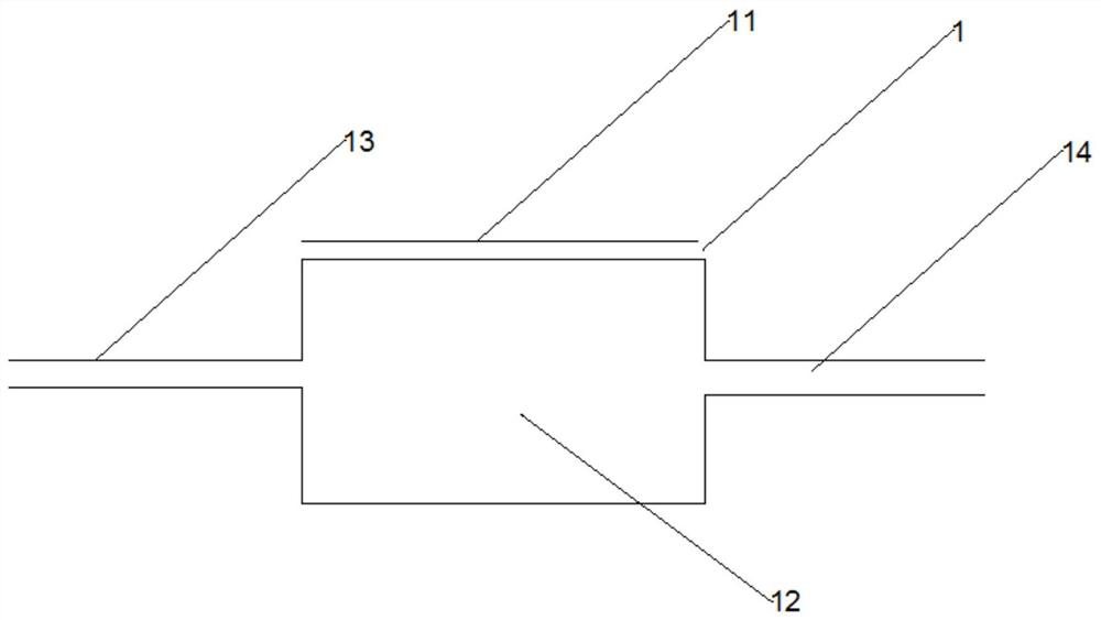
[0049] The application also provides an atomization system, specifically, such as Figure 2-4 As shown, the atomization system 1 includes an atomization sheet 11 and an atomization pool 12, the atomization sheet 11 can atomize the liquid in the atomization pool 12, and the atomization pool 12 is provided with an inlet 13. The outlet 14 and the atomizing port, the atomizing sheet 11 is arranged on the atomizing port, that is, the atomizing sheet 11 is not arranged on the outlet 14 . The atomization system 1 has a liquid inlet and a discharge port, the inlet 13 is the liquid inlet of the atomization system 1 ; the outlet 14 is the discharge port of the atomization system 1 .
[0050] Preferably, the atomizing sheet 11 is a microporous piezoelectric vibrating sheet.
[0051] Further, external liquid and / or gas can enter the atomization pool 12 from the inlet 13, and the liquid and / or gas in the atomization pool 12 can be discharged from the atomization pool through the outlet 14...
Embodiment 3
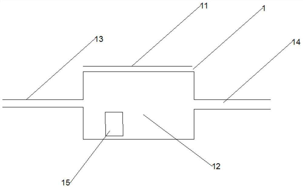
[0073] like Figure 2-4 As shown, an atomization system, the atomization system 1 includes an atomization sheet 11 and an atomization pool 12, and the atomization pool 12 is provided with an inlet 13 and an outlet 14.
[0074] Further, the atomization system 1 further includes a sensor, the sensor includes an in-pool sensor 15 located in the atomization pool 12, and the in-pool sensor 15 is configured to detect the liquid in the atomization pool 12 .
[0075] Furthermore, the sensor also includes an outside sensor 16 located outside the atomization pool 12 , and the outside sensor 16 is configured to detect the air outside the atomization pool 12 .
[0076] Preferably, the sensor 15 in the pool can detect the liquid level and properties of the liquid in the atomization pool 12, and the properties of the liquid include but not limited to the viscosity, temperature, surface tension, etc. of the liquid; the sensor 15 in the pool includes But not limited to viscosity sensors, te...
PUM
 Abstract
Description
Claims
Application Information
 - R&D
- Intellectual Property
- Life Sciences
- Materials
- Tech Scout
- Unparalleled Data Quality
- Higher Quality Content
- 60% Fewer Hallucinations
Browse by: Latest US Patents, China's latest patents, Technical Efficacy Thesaurus, Application Domain, Technology Topic, Popular Technical Reports.
© 2025 PatSnap. All rights reserved.Legal|Privacy policy|Modern Slavery Act Transparency Statement|Sitemap|About US| Contact US: help@patsnap.com