Rolling shaft type berth ground lock

A roller, ground lock technology, applied in the direction of roads, traffic restrictions, roads, etc., can solve the problems of evasion, scratching the chassis of the vehicle, no anti-collision function, etc., and achieve the effect of preventing evasion and avoiding scratches

Pending Publication Date: 2020-10-16
胡孟牛
View PDF2 Cites 0 Cited by
  • Summary
  • Abstract
  • Description
  • Claims
  • Application Information

AI Technical Summary

Problems solved by technology

[0003] Most of the existing parking locks are mechanical and manual. When the car enters or exits the parking space, it is necessary to get off the car to put down or prop up the pole of the parking lock, and then lock it, which is very inconvenient to use.
If it is an open-air parking space and it is raining, it will be even more troublesome.
In addition, manual parking locks have no anti-collision function. When encountering a collision, both the car and the parking lock are easily damaged.
[0004] In view of the deficiencies and defects of the existing technology, the inventor once proposed an invention patent application for a ground-embedded intelligent berth lock that is embedded below the ground, has no roadblocks, is easy to install, and locks the vehicle chassis (application number 201911248088.8; application publication number CN110735410A), but there are also the following disadvantages: 1. it is possible to scratch the chassis of the vehicle; 2. for vehicles with higher chassis such as off-road vehicles, it is possible to lock unreliably, causing phenomena such as escaping fees

Method used


Image

  • Rolling shaft type berth ground lock
  • Rolling shaft type berth ground lock
  • Rolling shaft type berth ground lock

Examples


Embodiment Construction

[0021] The specific implementation of the present invention will be further described below in conjunction with the accompanying drawings in the embodiments. Obviously, the described embodiments are only a part of the embodiments of the present invention, rather than all embodiments. For those of ordinary skill in the art, Other drawings can also be derived from these drawings without inventive effort.

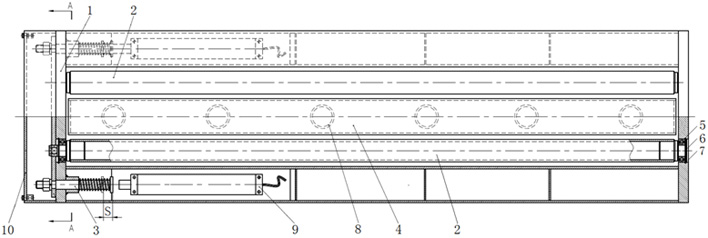
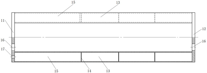
[0022] Such as Figure 1 ~ Figure 3 As shown, the roller-type berth lock includes a steel support frame 1, a roller shaft 2, and a locking mechanism 3. The steel support frame 1 is welded by the left main beam 11, the right main beam 12, the side beam 13, and the bottom plate 18. The formed frame structure has a roller installation hole 16 and a push rod installation hole 17 drilled on the left main beam 11, and a roller installation hole 16 is drilled on the right main beam 13, and the cross section of the side beam 13 is an undercut U-shaped, welded with stiffeners 14 in it...


PUM


Abstract

The invention relates to a rolling shaft type berth ground lock. The ground lock comprises a steel support frame, rolling shafts, a locking mechanism and a floating plate, the steel support frame is of a frame structure formed by assembling and welding a left main beam, a right main beam, side beams and a bottom plate. A rolling shaft mounting hole and a push rod mounting hole are drilled in the main beam on the left side; a rolling shaft mounting hole is drilled in the main beam on the right side; the cross section of the edge beam is in an inverted U shape, and a reinforcing rib plate is welded therein; a linear motor mounting interval is formed between the left main beam and the reinforcing rib plate, and a motor mounting seat is welded therein; two ends of each rolling shaft are mounted in rolling shaft mounting holes; the locking mechanism comprises a linear motor, a locking spring, a push rod and a locking plate, and the effective left movement stroke of the push rod is 22mm. Bylocking or separating the locking plate in the locking mechanism and the two rolling shafts, wheels are in a moving state or an idling state, a vehicle owner is prevented from evading fees, and a vehicle chassis can be prevented from being scratched.

Description

technical field [0001] The invention relates to the technical field of road parking charge management, in particular to a roller-type berth lock, which is applied to an open parking berth intelligent charge management system. Background technique [0002] With the rapid growth of car ownership, the problem of difficult parking in urban areas is very prominent. The current solution is to set parking spaces on roadsides and sidewalks in the central urban area, and to provide temporary paid parking services by locking the car through parking locks. [0003] Most of the existing parking locks are mechanical and manual. When the car enters or exits the parking space, it is necessary to get off the car and put down or prop up the pole of the parking lock, and then lock it, which is very inconvenient to use. If it is an open-air parking space and it is raining, it will be even more troublesome. In addition, manual parking locks have no anti-collision function. When encountering a...

Claims


Application Information

Patent Timeline
Patent Type & Authority Applications(China)
IPC IPC(8): E01F13/04
CPCE01F13/042
Inventor 胡孟牛
Owner 胡孟牛
Why Eureka
Try Eureka