
Grid flocculation sedimentation tank filled with diatomite

A technology of grid flocculation and sedimentation tank, which is applied in the direction of flocculation/sedimentation water/sewage treatment, water treatment parameter control, chemical instruments and methods, etc. Unstable water quality and other problems, to achieve the effect of saving dosage, saving dosage, and easy precipitation

Pending Publication Date: 2020-10-16
国能朗新明环保科技有限公司
View PDF0 Cites 3 Cited by
  • Summary
  • Abstract
  • Description
  • Claims
  • Application Information

AI Technical Summary

Problems solved by technology

However, the traditional grid flocculation sedimentation tank, regular sludge discharge, no sludge return, low removal efficiency of fine suspended solids of organic matter, and large fluctuations of suspended solids in the influent (especially when dealing with low temperature and low turbidity water), The water quality of the produced water is unstable and cannot meet the water quality requirements of the produced water
Moreover, when the temperature difference of the incoming water is large in a short period of time, it is easy to turn over the pool and affect the treatment effect

Method used


Image

  • Grid flocculation sedimentation tank filled with diatomite
  • Grid flocculation sedimentation tank filled with diatomite
  • Grid flocculation sedimentation tank filled with diatomite

Examples


Embodiment 1

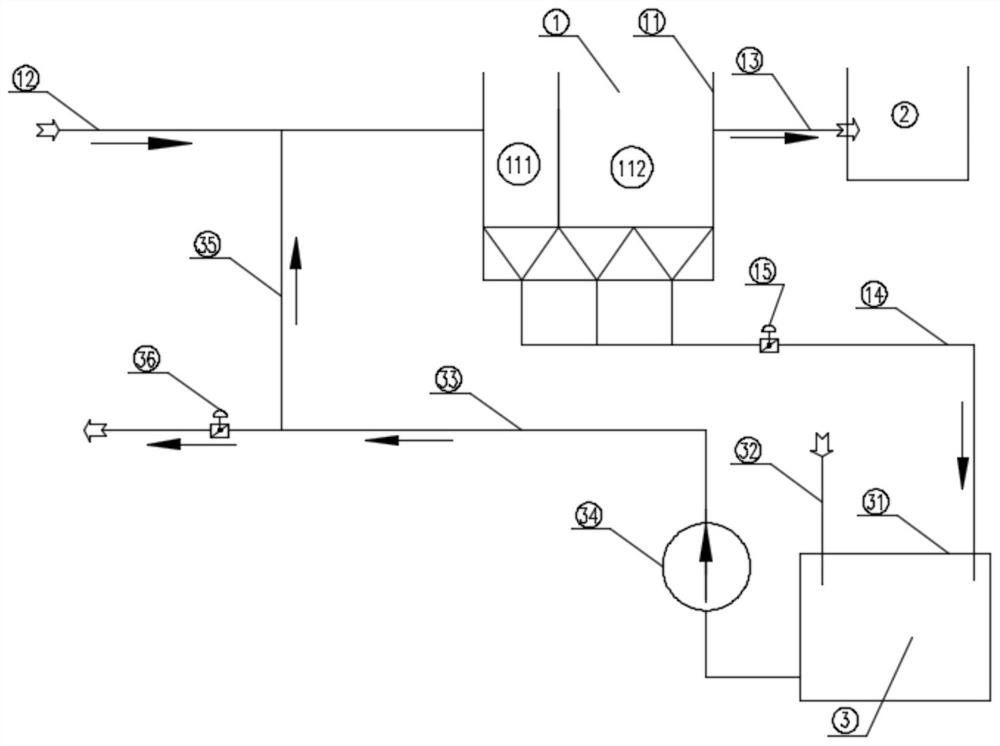
[0037] like figure 1 As shown, a grid flocculation sedimentation tank adding diatomite includes a grid flocculation sedimentation tank 1, a water production tank 2 connected to the grid flocculation sedimentation tank 1, and a sludge circulation tank 3.

[0038] The grid flocculation sedimentation tank 1 includes a grid flocculation sedimentation tank body 11, and the grid flocculation sedimentation tank body 11 includes a flocculation zone 111 and a sedimentation zone 112 arranged in the drainage direction of the flocculation zone 111;

[0039] The grid flocculation sedimentation tank 1 also includes a water inlet pipe 12 arranged on one side of the grid flocculation sedimentation tank body 11, and a water production pipe 13 arranged on the upper part of the grid flocculation sedimentation tank body 11 on the opposite side of the water inlet pipe 12. The bottom of the grid flocculation sedimentation tank body 11 is a main mud discharge pipe 14 formed by several branches of mu...

Embodiment 2

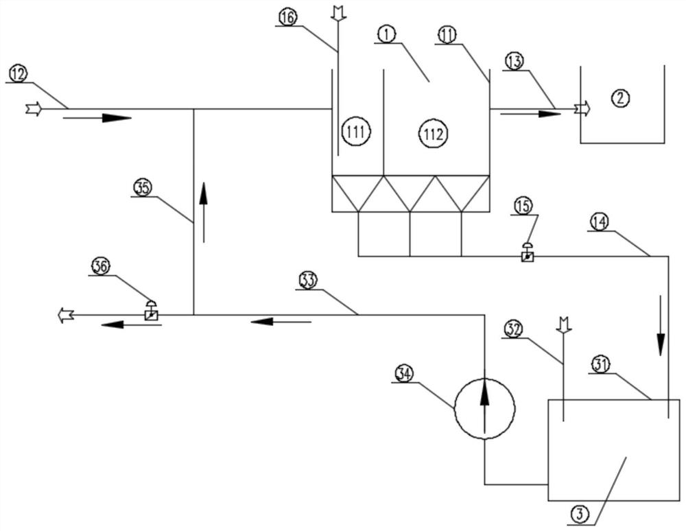
[0044] like figure 2 As shown, a grid flocculation sedimentation tank adding diatomite includes a grid flocculation sedimentation tank 1, a water production tank 2 connected to the grid flocculation sedimentation tank 1, and a sludge circulation tank 3.

[0045] The grid flocculation sedimentation tank 1 includes a grid flocculation sedimentation tank body 11, and the grid flocculation sedimentation tank body 11 includes a flocculation zone 111 and a sedimentation zone 112 arranged in the drainage direction of the flocculation zone 111;

[0046] The grid flocculation sedimentation tank 1 also includes a water inlet pipe 12 arranged on one side of the grid flocculation sedimentation tank body 11, and a water production pipe 13 arranged on the upper part of the grid flocculation sedimentation tank body 11 on the opposite side of the water inlet pipe 12. The bottom of the grid flocculation sedimentation tank body 11 is the main mud discharge pipe 14 formed by several branches of...

Embodiment 3

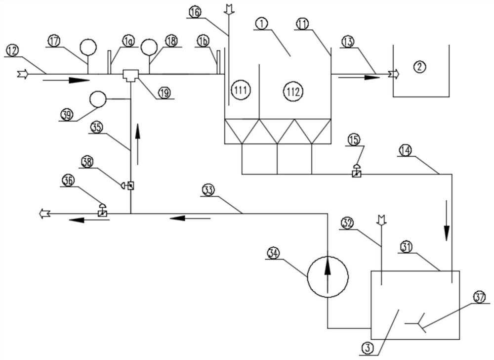
[0051] like image 3 As shown, a grid flocculation sedimentation tank adding diatomite includes a grid flocculation sedimentation tank 1, a water production tank 2 connected to the grid flocculation sedimentation tank 1, and a sludge circulation tank 3.

[0052] The grid flocculation sedimentation tank 1 includes a grid flocculation sedimentation tank body 11, and the grid flocculation sedimentation tank body 11 includes a flocculation zone 111 and a sedimentation zone 112 arranged in the drainage direction of the flocculation zone 111;

[0053] The grid flocculation sedimentation tank 1 also includes a water inlet pipe 12 arranged on one side of the grid flocculation sedimentation tank body 11. The water inlet pipe 12 is provided with a first flow meter 17 and a turbidity meter 18, and the water outlet of the first flow meter 17 is provided At one end of the water inlet of the turbidity meter 18, a tee 19 is provided on the water inlet pipe 12 between the first flow meter 17 ...


PUM


Abstract

The invention provides a grid flocculation sedimentation tank filled with diatomite. The tank comprises a grid flocculation sedimentation tank, a water production tank and a sludge circulation tank, awater production pipe of the grid flocculation sedimentation tank is connected with the water production tank, a sludge discharge pipe is connected with the sludge circulation tank, a dosing point ofthe sludge circulation tank is used for adding diatomite, and a sludge return pipe is used for returning sludge containing diatomite, a flocculating agent or a coagulant aid to the grid flocculationsedimentation tank. The invention aims to improve the pretreatment efficiency of low-temperature low-turbidity water and high-salt-content seawater and sewage and wastewater. The grid flocculation sedimentation tank which does not contain rotating equipment and is easy to prevent corrosion is selected; diatomite is added into the sludge circulation tank and sludge backflow is carried out; by utilizing the strong adsorption capacity of the diatomite to micro-floc organic matters, algae and the like in the water body, fine suspended particles which are difficult to remove by a conventional coagulating sedimentation process in the water are removed, meanwhile, the dosage is saved, the water inlet temperature difference can be reduced by adjusting the flow of returned sludge when the water inlet temperature difference is relatively large in a short time, and the tank is prevented from being turned over.

Description

technical field [0001] The invention relates to the technical field of water treatment, in particular to a grid flocculation sedimentation tank with diatomite added. Background technique [0002] With the development of economy and the increase of population in my country, the demand for water resources of human beings continues to increase, coupled with the regional differences in the distribution of water resources, the shortage of water and the shortage of water resources in the region caused by the less distribution of water resources in local areas. Deterioration of physical form or water quality makes water resources unusable, resulting in varying degrees of water shortages in various regions. Water shortage is mainly divided into two aspects: resource water shortage and water quality water shortage. At present, to solve the problem of resource water shortage, the main method is to develop and utilize some unavailable water. The main method is seawater desalination, es...

Claims


Application Information

Patent Timeline
Patent Type & Authority Applications(China)
IPC IPC(8): C02F1/52C02F1/28C02F101/30
CPCC02F1/281C02F1/5236C02F1/5263C02F2101/30C02F2209/02
Inventor 曲艳春陈艳艳徐志清王凤雷
Owner 国能朗新明环保科技有限公司
Learn More