
Clamping tool for loading and unloading oversized polycrystalline silicon rods

A super-large polysilicon, clamping tooling technology, applied in the direction of silicon compounds, inorganic chemistry, non-metallic elements, etc., can solve the problem of unbearable polysilicon rods, silicon rods detachment, cutting, etc., to achieve excellent structural performance and stable clamping effect.

Pending Publication Date: 2020-10-16
新疆东方希望新能源有限公司
View PDF10 Cites 0 Cited by
  • Summary
  • Abstract
  • Description
  • Claims
  • Application Information

AI Technical Summary

Problems solved by technology

At this time, due to the uniform thickness of the jaws in the traditional clamping tool, it is often difficult for the uppermost jaw to penetrate into the upper gap between the rods on both sides, resulting in difficulty in clamping
[0004] However, if the technical scheme of reducing the thickness of the jaws to adapt to the change in the gap size is adopted, the overall weight load will increase because the average diameter of the super polysilicon rod deposition increases; when the movable end of the mechanical arm in the clamping tooling drives the entire polysilicon rod After turning over to a horizontal state, the thinner jaws are often difficult to bear the load of the polysilicon rod, so it is easy to cause failures such as silicon rod detachment and jaw damage

Method used


Image

  • Clamping tool for loading and unloading oversized polycrystalline silicon rods
  • Clamping tool for loading and unloading oversized polycrystalline silicon rods
  • Clamping tool for loading and unloading oversized polycrystalline silicon rods

Examples


Embodiment 1

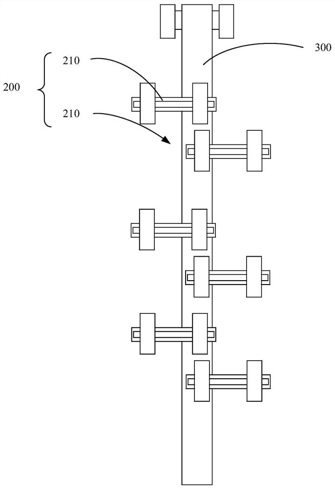
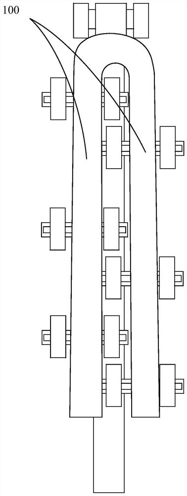
[0038] see figure 1 , figure 2 and image 3 , are respectively a structural schematic diagram of a clamping tool for loading and unloading super polysilicon rods provided in Embodiment 1, and a schematic diagram of clamping super polysilicon rods.

[0039]Among them, the polysilicon rod is mainly composed of two rod bodies 100 placed on the left and right sides, which are in a vertical state in the reduction furnace, and the clamping tool is mainly used to hold the polysilicon rod in the reduction furnace, and then Driven by the movable end 300 of the mechanical arm, it turns over to a horizontal state for conveying.

[0040] The clamping tooling in the present embodiment 1 includes a base (not shown), a mechanical arm (not shown) whose fixed end is connected to the base, and is arranged on the movable end of the mechanical arm in turn along the extension direction of the rod body 100. Several groups of clamping groups 200 on the 300; each group of clamping groups 200 incl...

Embodiment 2

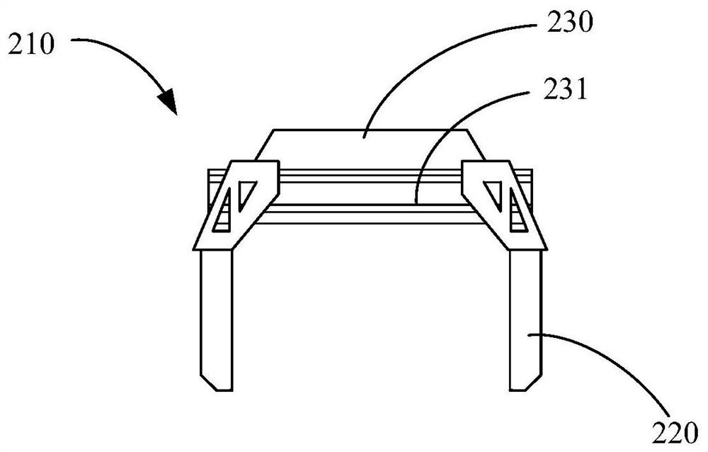
[0047] Embodiment 2 is substantially the same as Embodiment 1, and the main difference between the two lies in the structural details of the jaws 220 .

[0048] see Figure 4 to Figure 7 , in Embodiment 2, the jaw 220 is mainly composed of a moving steel frame for sliding connection with the first chute 231, and an elastic contact layer 222 for contacting the corresponding side wall of the rod body 100; A connecting plate 221 is formed on the moving steel frame, and the elastic contact layer 222 covers the connecting plate 221 and is fixedly connected to the connecting plate 221 by bolts. Compared with the clamping jaw 220 made of polyurethane material, the clamping jaw 220 is divided into a moving steel bar slidingly connected with the first chute 231 and an elastic contact layer 222 specially used for contacting the rod body 100 According to the setting method, since the connecting plate 221 on the moving steel frame is a steel structure, its stability and reliability are m...


PUM


Abstract

The invention discloses a clamping tool for loading and unloading oversized polycrystalline silicon rods. The invention relates to the technical field of silicon rod manufacturing through a Siemens method. The thicknesses of clamping jaw are mainly optimized and improved, the thicknesses of the clamping jaws in each clamping group are reduced group by group in the direction from bottom to top, theclamping jaws on the upper side can effectively adapt to polycrystalline silicon rods with small upper rod body gaps, meanwhile, the thicknesses of the clamping jaws on the lower side can effectivelybear the load of the polycrystalline silicon rods, and stable clamping of the oversized polycrystalline silicon rods is achieved.

Description

technical field [0001] The invention relates to the technical field of manufacturing silicon rods by the Siemens method, in particular to a clamping tool for loading and unloading super polycrystalline silicon rods. Background technique [0002] Polysilicon has semiconductor properties and is an extremely important excellent semiconductor material. It is widely used in the electronics industry to manufacture semiconductor radios, tape recorders, refrigerators, color TVs, video recorders, electronic computers and other products. With the advancement of polysilicon production technology and the increase of polysilicon deposition speed, polysilicon production enterprises are more concerned about increasing production and efficiency, and the diameter of polysilicon finished products is getting larger and larger. Polysilicon rods. [0003] While these ultra-polysilicon rods improve the production efficiency of enterprises, they also pose a problem to the clamping tooling. Specif...

Claims


Application Information

Patent Timeline
IPC IPC(8): C01B33/035
CPCC01B33/035
Inventor 简凤麟梁瑞锋成章文罗家斌邹分红梁国东刘彦东薛兵兵柴璐斌
Owner 新疆东方希望新能源有限公司
Learn More