Eureka AIR delivers breakthrough ideas for toughest innovation challenges, trusted by R&D personnel around the world.

Lightweight anti-static foam pump and material production process thereof

A foam pump and anti-static technology, which is applied to sealing parts with unloading devices, closing, packaging, etc., can solve the problems of lack of double-piston and connecting seat structural design, material production process needs to be improved, and poor overall structural design, etc. , to achieve the effects of good sealing, convenient production, and small space occupation of pump body height

Pending Publication Date: 2020-10-16
ZHEJIANG Z&Z IND CO LTD
View PDF1 Cites 2 Cited by
  • Summary
  • Abstract
  • Description
  • Claims
  • Application Information

AI Technical Summary

Problems solved by technology

[0003] In order to overcome the above-mentioned deficiencies, the purpose of the present invention is to provide a lightweight anti-static foam pump and its material production process in the field, so that it can solve the unreasonable design of the space in the pump body of existing similar products, resulting in poor overall structural design. In particular, the lack of structural design of double pistons and connecting seats, and the technical problems that the material production process needs to be improved

Method used


Image

  • Lightweight anti-static foam pump and material production process thereof
  • Lightweight anti-static foam pump and material production process thereof
  • Lightweight anti-static foam pump and material production process thereof

Examples


Embodiment Construction

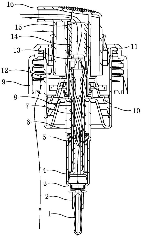
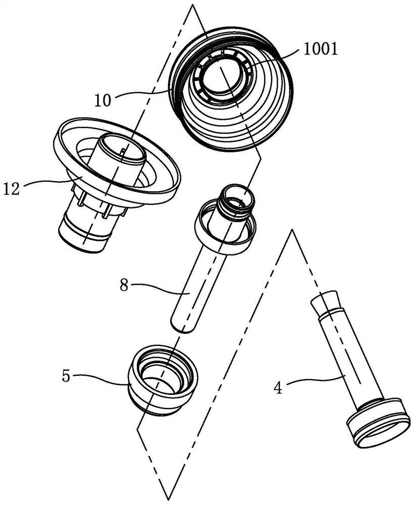
[0020] Now in conjunction with accompanying drawing, the present invention will be further described. Such as Figure 1-Figure 6 As shown, the outer diameter of the inner ring diameter of the large ring 9 of the foam pump is sleeved in the inner diameter of the pump port of the pump body 2, and at the same time the outer diameter of the pump port of the pump body and the inner ring diameter of the large ring fit together with the ribs, and the fitting place A gasket 11 is provided, and the pump body is provided with a piston, a spring pad 5, a connecting seat 12, a valve stem 8, a valve needle 7, a spring 6 and an elastic sleeve 3, and the elastic sleeve is arranged at the water inlet hole in the pump body. The water inlet hole is provided with a suction pipe 1, and the shrapnel in the middle of the bullet sleeve is against the orifice of the water inlet hole in the pump body. The valve stem protruding from the pump body is connected to the duckbill 16 through the connecting s...


PUM


Abstract

The invention relates to a lightweight anti-static foam pump and a material production process thereof. The pump and the process are designed aiming at the technical problems that the design of an inner space of a pump body of an existing similar product is not reasonable and the design of a double-piston and connecting seat structure is lacking. The key point is that an piston in a pump body comprises a large piston and a small piston, a valve needle is arranged into an inner through hole of a valve rod from one end of the valve rod in a sleeving mode, meanwhile, the valve needle in the valverod is buckled and fixedly connected with one end of the small piston arranged with the other end of the valve rod in a sleeving mode, the connecting part, the rod part of the small piston buckled and fixed with the valve needle, of a valve rod outer diameter is arranged with a spring pad in a sleeving mode, a valve needle sleeved end outer diameter of the valve rod is provided with a ring rib, one end of a spring abuts against the ring rib of the valve rod, and the other end of the spring abuts against the spring pad; and an outer diameter of the small piston is abutted and sealed with the thin inner cavity wall above an elastic sleeve of the pump body, an outer diameter of the large piston is abutted and sealed with the large inner cavity wall above a thin inner cavity in the pump body,a duckbill is connected with the valve rod through a connecting seat, the outer diameter of a blade ring of the large piston is provided with a vent groove, and the height of the pump body of a foampump is small.

Description

technical field [0001] The invention relates to a miniature foam pump, which is a lightweight anti-static foam pump and a material production process thereof. Background technique [0002] Foam pump is a kind of pump body that can produce foam spraying. According to its use and size, it is generally divided into industrial foam pump, fire fighting foam pump, and micro foam pump. Among them, the working principle of the micro foam pump is to use the liquid to form a certain negative pressure around the liquid column after being sprayed out at high speed, and the negative pressure generates to attract the gas into the mixing part, so that the air and liquid are mixed again and quickly pass through the screen to form foam. . This type of foam pump is mainly used in cosmetic bottle containers such as facial cleanser. For example, the application number 201610345084.1 published in the Chinese patent literature, the application publication date is 2016.09.07, and the invention na...

Claims


Application Information

Patent Timeline
IPC IPC(8): B65D47/24B65D47/34C08L67/02C08L67/04C08K13/02C08K3/22C08K3/04
CPCB65D47/247C08L67/02C08L67/04B65D2547/063C08L2205/035C08L2205/02C08K2201/011C08K2003/2241C08L2201/04C08K13/02C08K3/22C08K3/042
Inventor 黄建艺
Owner ZHEJIANG Z&Z IND CO LTD
Why Eureka
Eureka Blog
Learn More