An aircraft and its rotor head assembly

A technology of rotor head and components, which is applied in the field of aircraft, can solve problems such as the inability to apply single-rotor aircraft, and achieve the effect of changing the flight attitude

Active Publication Date: 2021-11-23
陈维康
View PDF8 Cites 0 Cited by
  • Summary
  • Abstract
  • Description
  • Claims
  • Application Information

AI Technical Summary

Problems solved by technology

However, it is precisely because of the limitation of this structure that it cannot be applied to single-rotor aircraft.

Method used


Image

  • An aircraft and its rotor head assembly
  • An aircraft and its rotor head assembly
  • An aircraft and its rotor head assembly

Examples


Embodiment 2

[0060] Embodiment 2 of an aircraft of the present invention, such as Figure 11 to Figure 13 As shown: in this embodiment, there are four propellers 1, which are evenly distributed in the circumferential direction on the power transmission assembly 2, and the connection relationship between the two opposite propellers is the same as that in embodiment 1.

[0061] For the rotor head structure with four or more propellers, the control principle is that the total lift in a semicircle at a certain moment is greater than the total lift in another semicircle to achieve attitude control of the aircraft. For example for Figure 12 and Figure 13 As shown, the four-bladed propeller structure, assuming that the motor rotates counterclockwise, accelerates when the No. 1 propeller points to A and decelerates when the No. 1 propeller points to B, the lift force in the fan-shaped BAD can be greater than that in the fan-shaped BCD , so as to generate a lift difference on the rotating plane...

Embodiment 3

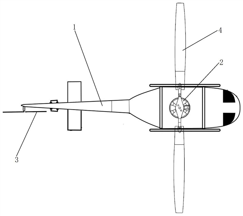
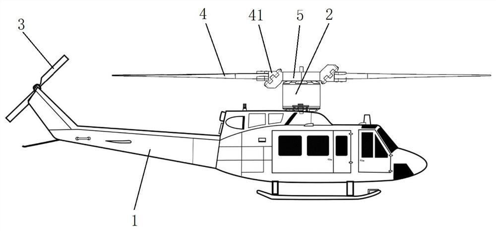
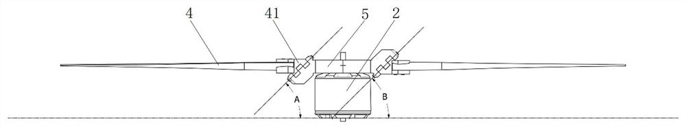
[0062] Embodiment 3 of an aircraft of the present invention, such as Figure 11 to Figure 13 As shown: the power transmission assembly includes a rotating base 1 and a mounting part 3 for connecting with the power device, the propeller is hingedly arranged on the mounting part 3, the mounting part 3 is hingedly connected with the rotating base 1 and the axis of the hinge shaft 2 extends along the horizontal direction .

[0063] The swivel base includes two opposite vertical plates 11, and the mounting part is hingedly arranged between the two vertical plates. In this embodiment, there are two propellers, and the two propellers are arranged opposite to each other on the mounting part. At the same time, the projection of the extension line of the axis of the hinge shaft of the mounting part in the horizontal direction and the extending direction of the propeller are in the horizontal direction. projections intersect. In this way, when the propellers are rotating, when they acc...


PUM


Abstract

The present invention relates to the field of aircraft, in particular to an aircraft and a rotor head assembly thereof. The aircraft of the present invention includes a power transmission assembly for connecting with a power device and two or more propellers arranged on the power transmission assembly in pairs, the propellers and the power transmission assembly are hingedly connected, and the two oppositely arranged propellers and the power transmission assembly are between the propellers. The hinge shafts are inclined in the same direction. During operation, when the rotor rotates at a constant speed, the power transmission assembly drives the propeller to rotate at a constant speed; when the rotor rotates at a variable speed, under the action of inertia, the propeller will be relative to the power transmission assembly. The shaft swings, and the swing directions of the two oppositely arranged propellers are opposite, so that the pitch of one of the propellers becomes larger, and the pitch of the other propeller becomes smaller, which changes the direction of the lift of the rotors, thereby changing the flight attitude of the aircraft.

Description

technical field [0001] The invention relates to the field of aircraft, in particular to an aircraft and a rotor head assembly thereof. Background technique [0002] Helicopter is a kind of aircraft. The current helicopter rotor control system is realized based on complex mechanical structure. The mechanical structure of the rotor head realizes the change of the cyclic pitch through the steering gear to control the flight attitude of the helicopter. This rotor head structure Complicated, affecting stability and volume. [0003] In the prior art, there is also a rotor head structure with a relatively simple structure, which is mainly used for multi-rotor aircraft, such as a rotor device disclosed in a Chinese patent document with an authorized announcement number of CN105059536B: it has a power device with an output shaft; at least two a propeller; the transmission assembly has at least two rotating shafts that form an angle with the output shaft; wherein, the power device ac...

Claims


Application Information

Patent Timeline
Patent Type & Authority Patents(China)
IPC IPC(8): B64C27/12B64C27/06B64C27/39B64C27/59B64C27/80
CPCB64C27/06B64C27/12B64C27/39B64C27/59B64C27/80
Inventor 陈维康
Owner 陈维康
Why Eureka
Try Eureka