a wheel rotor

A rotor and wheel technology, applied in the field of aircraft, can solve problems affecting the development speed and achieve the effect of changing the flight attitude

Active Publication Date: 2019-05-31
北京零创众成科技有限公司
View PDF6 Cites 0 Cited by
  • Summary
  • Abstract
  • Description
  • Claims
  • Application Information

AI Technical Summary

Problems solved by technology

At present, most flying cars provide lift through the rotors installed on the body, but the size of the rotors is huge and it is difficult to arrange them in a compact body. Therefore, the development of flying cars brings a bottleneck and affects the development speed.

Method used


Image

  • a wheel rotor
  • a wheel rotor
  • a wheel rotor

Examples


Embodiment Construction

[0015] The following will describe in detail with reference to the accompanying drawings in the embodiments of the present invention.

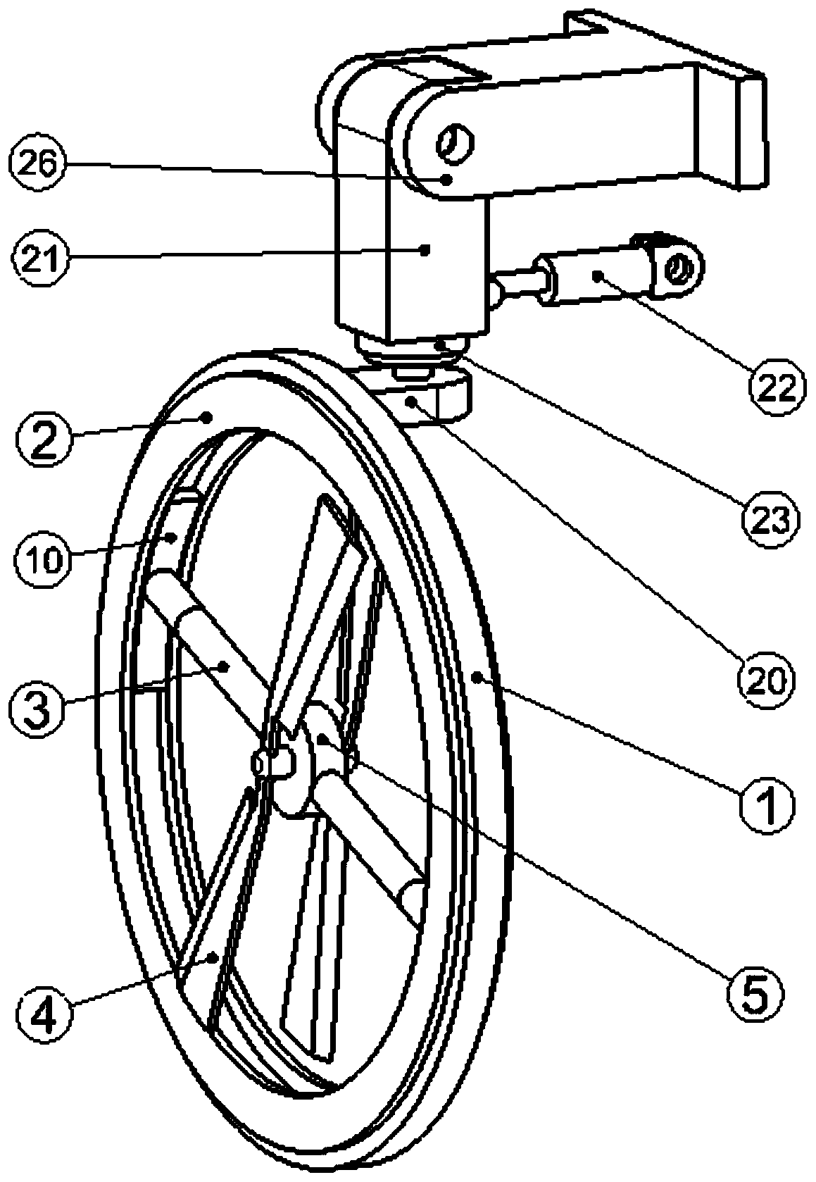
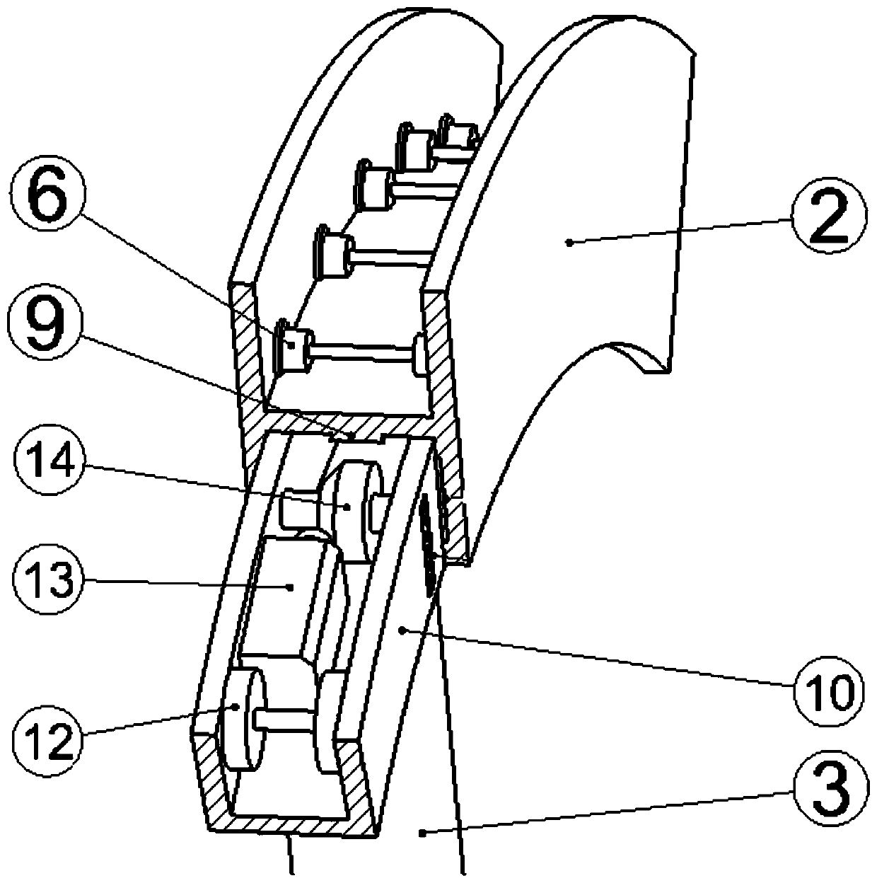
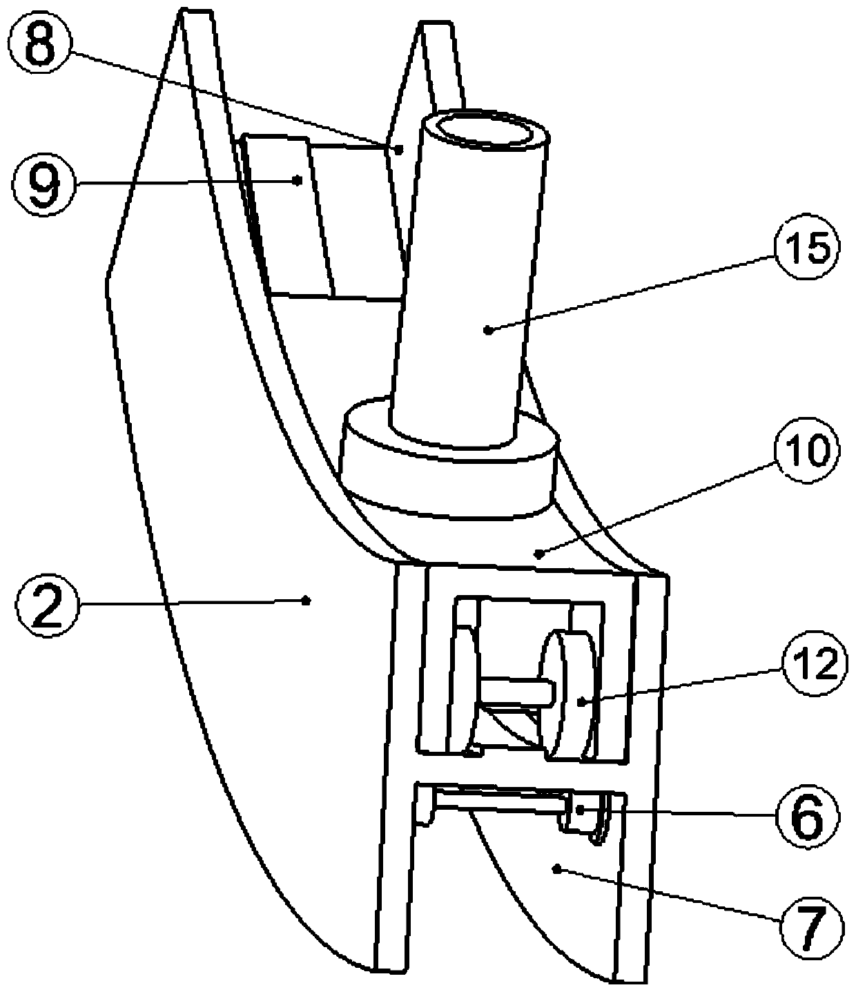
[0016] see figure 1 , figure 2 , image 3 , Figure 4 , Figure 5 , the variable rotor wheel is mainly composed of: ring wheel 1, ring frame 2, rotor bracket 3, rotor 4, rotor motor 5; the outer wall of the ring frame 2 is provided with a wheel groove 7 in the circumferential direction, and a number of wheel bearings are uniformly arranged in the wheel groove 7 6. The annular wheel 1 is set in the wheel groove 8, constrained by the bearing 6, and can freely rotate in the wheel groove 7. A tubular rotor support 3 coaxial with the diameter is arranged horizontally in the ring frame 2 . The inner wall of the ring frame 2 is provided with a circumferential slide block groove 8 and teeth 9, the first slide block 10 and the second slide block 11 are arranged in the slide block groove 8, and the first slide block 10 and the second slide block 1...


PUM


Abstract

The invention relates to the field of aircrafts, in particular to a variable rotor wheel of an aerocar. The rotor wheel is mainly composed of an annular wheel, an annular frame, a rotor support, rotors and a rotor motor. By means of the variable rotor wheel of the aerocar, the rotor storage problem of a rotor-type aerocar is solved, the rotors are ingeniously combined with the wheel, the rotors can be turned out in the traveling state of the aerocar, the traveling state is smoothly transformed into a flying state, and through the angle variation of the rotor support and the rotation speed variation of the rotors, control can reach an extremely sensitive degree during flying and flying postures can be changed in a multi-angle mode.

Description

technical field [0001] The invention relates to the field of aircraft, in particular to a variable-rotor wheel installed on a flying car. Background technique [0002] In the current aircraft field, flying cars have gradually become a new development direction for the combination of aircraft and vehicles. At present, most flying cars provide lift through the rotors installed on the body, but the size of the rotors is huge and it is difficult to arrange them in a compact body. Therefore, the development of flying cars brings a bottleneck and affects the development speed. Contents of the invention [0003] The purpose of the present invention is to provide a variable-rotor wheel to solve the problem of the installation and arrangement of the flying car rotor and wheels in the above-mentioned background technology. In order to achieve the above object, the present invention provides the following technical solutions: the variable rotor wheel is mainly composed of: ring whee...

Claims


Application Information

Patent Timeline
Patent Type & Authority Patents(China)
IPC IPC(8): B60F5/02B60B19/00
CPCB60B19/00B60F5/02
Inventor 马小山周大围廖子维邰鑫来
Owner 北京零创众成科技有限公司
Why Eureka
Try Eureka