
Workpiece main shaft and grinding machine tool

A workpiece spindle and electric spindle technology, which is applied to the parts of grinding machine tools, grinding/polishing equipment, manufacturing tools, etc., can solve the problem of difficult to achieve ultra-precision machining accuracy, poor coaxiality of inner circles at both ends, and workpiece spindle positioning Accuracy, rotation accuracy, radial stiffness and axial stiffness cannot meet the requirements of precision and ultra-precision grinding processing, etc., to meet the processing requirements of precision and ultra-precision grinding, improve processing accuracy, and improve the effect of workpiece surface quality

Inactive Publication Date: 2020-10-16
GUANGZHOU HAOZHI ELECTROMECHANICAL
View PDF9 Cites 1 Cited by
  • Summary
  • Abstract
  • Description
  • Claims
  • Application Information

AI Technical Summary

Problems solved by technology

At present, for precision and ultra-precision internal grinding, it is usually single-sided grinding. When both ends of the workpiece need to be ground, it is necessary to turn around and clamp, resulting in poor coaxiality of the inner circles at both ends.
Especially for long workpieces such as bodies or sleeves, the machining accuracy is difficult to meet the ultra-precision requirements due to U-turn processing
[0003] The positioning accuracy, rotation accuracy, radial stiffness and axial stiffness of the workpiece spindle of the existing grinding machine cannot meet the processing requirements of precision and ultra-precision grinding

Method used


Image

  • Workpiece main shaft and grinding machine tool
  • Workpiece main shaft and grinding machine tool

Examples


Embodiment Construction

[0034] This part will describe the specific embodiment of the present invention in detail, and the preferred embodiment of the present invention is shown in the accompanying drawings. Each technical feature and overall technical solution of the invention, but it should not be understood as a limitation on the protection scope of the present invention.

[0035] In the present invention, if there is a description of directions (up, down, left, right, front and back), it is only for the convenience of describing the technical solution of the present invention, rather than indicating or implying that the referred technical features must have specific Orientation, construction and operation in a particular orientation, therefore should not be construed as limiting the invention.

[0036] In the present invention, "several" means one or more, "multiple" means more than two, "greater than", "less than", "exceeding", etc. are understood as excluding the original number; "above", "belo...


PUM


Abstract

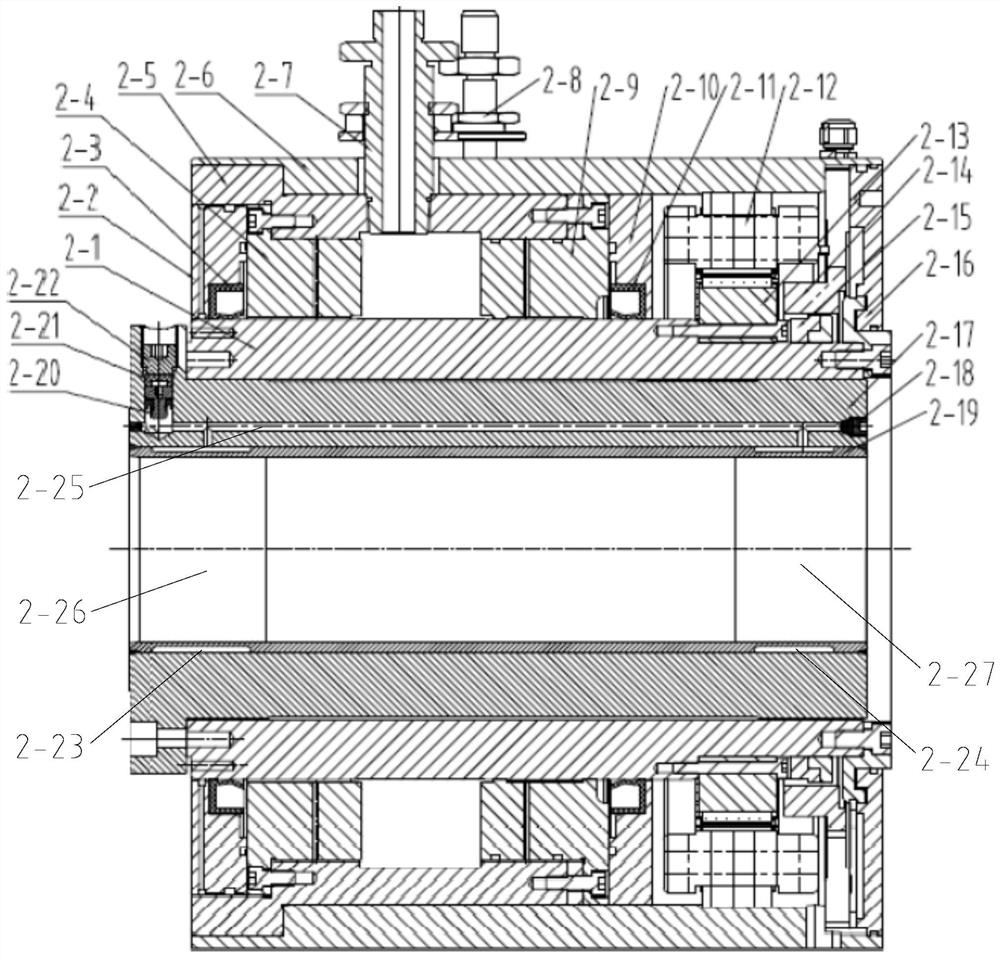
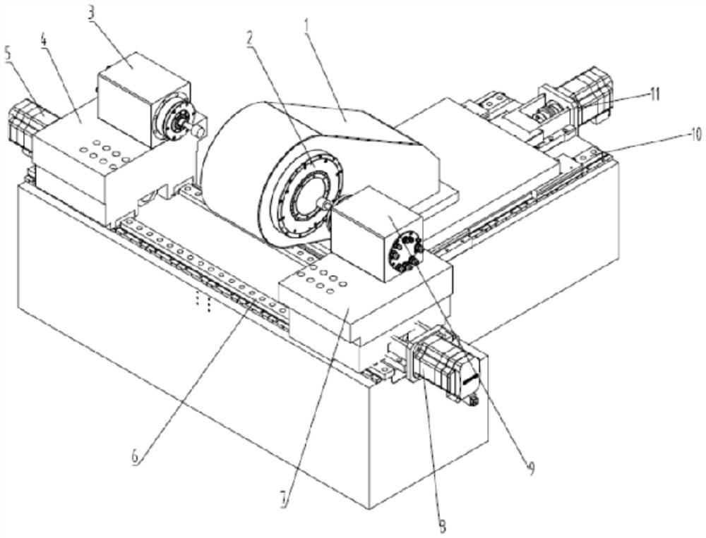
The invention discloses a workpiece main shaft and a grinding machine tool. The workpiece main shaft comprises a main shaft outer sleeve, a shaft core, a hydraulic clamping device and a motor assembly, wherein the shaft core is positioned inside the main shaft outer sleeve and is supported by a hydrostatic bearing, the shaft core is provided with a shaft core inner hole, the hydraulic clamping device comprises an expansion sleeve, the expansion sleeve is arranged in the shaft core inner hole, the expansion sleeve is directly or indirectly connected with the shaft core, the expansion sleeve iselastically deformed through hydraulic oil to clamp a workpiece, and the motor assembly is used for driving the shaft core to rotate. The grinding machine tool comprises the workpiece main shaft. By adopting the hydrostatic supporting structure, the workpiece main shaft is high in rotation precision, and improved in radial stiffness and axial stiffness; a liquid medium oil film between the shaft core and the hydrostatic bearing is large in damping, so that the vibration of the workpiece main shaft in the machining process is reduced, and the rotation stability of the workpiece main shaft is improved; and the hydraulic clamping device adopts the principle of elastic deformation of the expansion sleeve to clamp the workpiece, so that the advantages of stable and reliable in clamping, high inpositioning precision, convenient in operation and the like are realized, and the machining requirements of precise and ultra-precise grinding can be better met.

Description

technical field [0001] The invention is used in the field of mechanical processing, and in particular relates to a workpiece spindle and a grinding machine tool. Background technique [0002] A grinder is a machine tool that uses abrasive tools to grind the surface of a workpiece. At present, for precision and ultra-precision internal grinding, it is usually single-sided grinding. When both ends of the workpiece need to be ground, it is necessary to turn around and clamp, resulting in poor coaxiality of the inner circles at both ends. Especially for long workpieces such as bodies or sleeves, it is difficult to achieve ultra-precision machining accuracy due to U-turn processing. [0003] The positioning accuracy, rotation accuracy, radial stiffness and axial stiffness of the workpiece spindle of the existing grinding machine cannot meet the processing requirements of precision and ultra-precision grinding. Contents of the invention [0004] The purpose of the present inve...

Claims


Application Information

Patent Timeline
Patent Type & Authority Applications(China)
IPC IPC(8): B24B41/04
CPCB24B41/04
Inventor 郭晶晶汤丽君张翰乾汤秀清
Owner GUANGZHOU HAOZHI ELECTROMECHANICAL
Learn More