
Knee joint system, tibial prosthesis, tibial tray prosthesis series and tibial tray prosthesis group

A technology of supporting prosthesis group and tibial tray, applied in the directions of knee joint, elbow joint, joint implant, etc., can solve the problem of destroying the integrity of the new column hole and keel groove, affecting the stability of the tibial tray prosthesis fixation, and increasing the tibia Prosthesis loosening probability and other problems, to achieve the effect of reducing the probability of infection, reducing the probability of loosening, and reducing the operation time

Pending Publication Date: 2020-10-16
SUZHOU MICROPORT ORTHORECON CO LTD
View PDF0 Cites 1 Cited by
  • Summary
  • Abstract
  • Description
  • Claims
  • Application Information

AI Technical Summary

Problems solved by technology

However, the traditional tibial tray prosthesis needs to re-drill the column hole and the keel slot when the model is changed, and because the columns and keel positions of the adjacent tibial tray prosthesis are relatively close, when re-drilling the column hole and the keel slot , the original post holes and keel slots will destroy the integrity of the new post holes and keel slots, affect the fixation stability of the tibial tray prosthesis, and increase the probability of tibial tray prosthesis loosening

Method used


Image

  • Knee joint system, tibial prosthesis, tibial tray prosthesis series and tibial tray prosthesis group
  • Knee joint system, tibial prosthesis, tibial tray prosthesis series and tibial tray prosthesis group
  • Knee joint system, tibial prosthesis, tibial tray prosthesis series and tibial tray prosthesis group

Examples


Embodiment Construction

[0033] In order to make the above objects, features and advantages of the present invention more comprehensible, specific implementations of the present invention will be described in detail below in conjunction with the accompanying drawings. In the following description, numerous specific details are set forth in order to provide a thorough understanding of the present invention. However, the present invention can be implemented in many other ways different from those described here, and those skilled in the art can make similar improvements without departing from the connotation of the present invention, so the present invention is not limited by the specific embodiments disclosed below.

[0034] In order to better illustrate the technical solution of the present invention, first, the names of directions that may be involved in each embodiment are explained:

[0035] Sagittal plane: refers to the longitudinal section that divides the human body or prosthesis into left and r...


PUM


Abstract

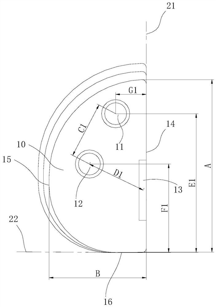
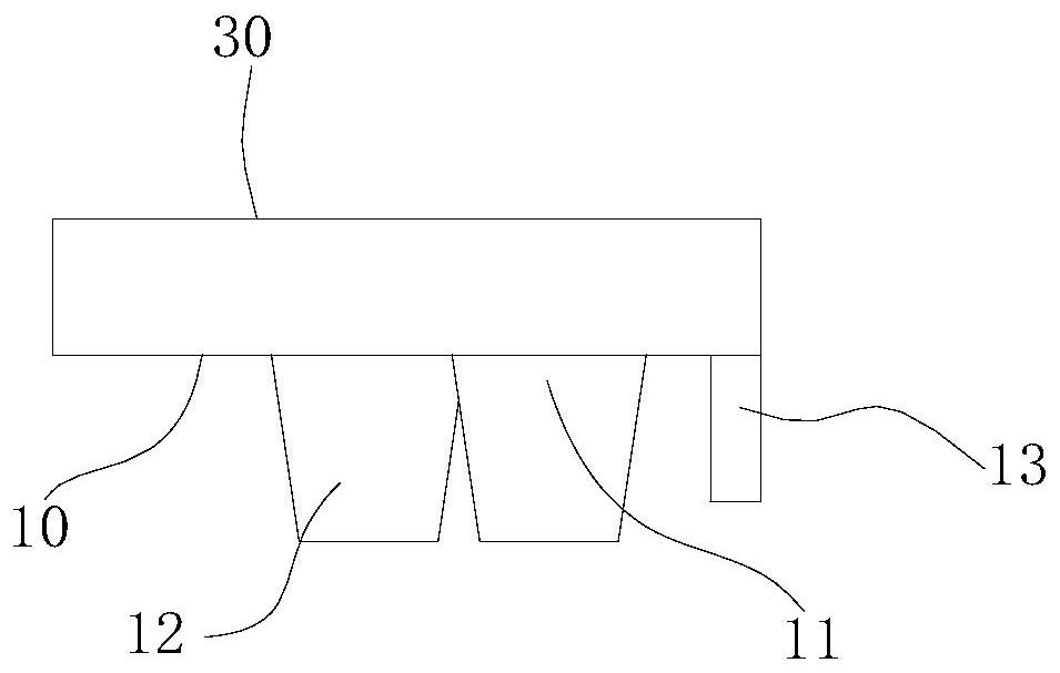
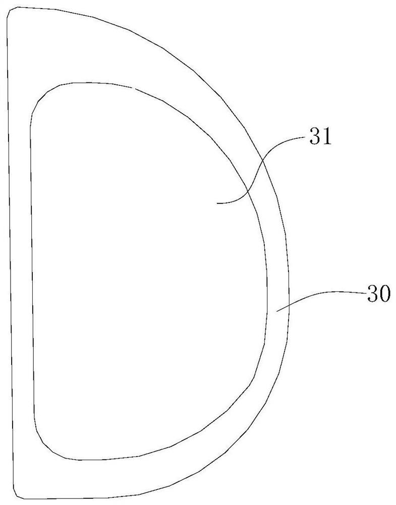
The invention relates to a knee joint system, a tibial prosthesis, a tibial tray prosthesis series and a tibial tray prosthesis group. The tibial tray prosthesis group comprises at least two tibial tray prostheses of different models, wherein each tibial tray prosthesis is provided with a stand column connected with a tibia and a keel; each tibial tray prosthesis is further provided with a first reference surface and a second reference surface; the second reference surface is intersected with the first reference surface; and when the first reference surfaces of the tibial tray prostheses of different models are aligned and the second reference surfaces are aligned, the stand columns of the tibial tray prostheses of different models are overlapped and the keels are overlapped. According tothe tibial tray prosthesis group, the fixing stability of the tibial tray prostheses is improved and the loosening probability of the tibial tray prostheses is reduced. Meanwhile, stand column holes and keel 13 grooves do not need to be formed again so that the operation efficiency is also improved, the operation time is shortened and the infection probability of patients is reduced.

Description

technical field [0001] The invention relates to the technical field of medical devices, in particular to a knee joint system, a tibial prosthesis, a tibial tray prosthesis series and a tibial tray prosthesis group. Background technique [0002] Unicompartmental replacement uses a minimally invasive incision while preserving the anterior and posterior cruciate ligaments of the knee joint. It has the advantages of less trauma, faster recovery, and better postoperative physiological activity. Therefore, unicompartmental replacement is widely used in unicompartmental surgery. In the treatment of osteoarthritis. The unicompartmental knee prosthesis used in unicompartmental replacement includes the femoral condyle prosthesis for replacing the diseased bone tissue of the distal femur, the tibial tray prosthesis for replacing the diseased bone tissue of the proximal tibia, and the replacement of the meniscus to achieve Tibial padding to reduce friction and wear. [0003] During a ...

Claims


Application Information

Patent Timeline
IPC IPC(8): A61F2/38
CPCA61F2/38A61F2/389A61F2/3859
Inventor 孙延东赵开宇史忠兵熊文涛
Owner SUZHOU MICROPORT ORTHORECON CO LTD
Learn More