
Virtual reality interaction method and virtual reality interaction device

A technology of virtual reality and interactive methods, applied in image data processing, instruments, electrical digital data processing, etc., can solve problems such as low action accuracy, large user operation limitations, and the camera cannot capture hand movements, etc. The algorithm is simple and the effect of interaction is convenient

Pending Publication Date: 2020-10-13
HISENSE VISUAL TECH CO LTD
View PDF5 Cites 0 Cited by
  • Summary
  • Abstract
  • Description
  • Claims
  • Application Information

AI Technical Summary

Problems solved by technology

[0012] This method requires the user to ensure that the hand is within the field of view of the camera, which limits the user's operation; and the user's eyes are covered by the virtual reality device, so it is difficult to accurately determine the field of view of the camera, and it is very likely that the hand Extending the field of view to perform actions causes the camera to fail to capture hand movements; moreover, the field of view of the camera is generally facing the front of the user. In order to ensure that the camera can fully capture the hand movements, the user needs to stretch out the hand for a long time to perform operations, and the operation is also difficult. There are many inconveniences; in addition, the accuracy of user actions in current image acquisition is low, and it is difficult to respond accurately according to user actions
[0013] It can be seen that there are many inconveniences and limitations in the operation of several current ways to realize the interaction between virtual reality equipment and wearers.

Method used


Image

  • Virtual reality interaction method and virtual reality interaction device
  • Virtual reality interaction method and virtual reality interaction device
  • Virtual reality interaction method and virtual reality interaction device

Examples


Embodiment Construction

[0066] Reference will now be made in detail to the exemplary embodiments, examples of which are illustrated in the accompanying drawings. When the following description refers to the accompanying drawings, the same numerals in different drawings refer to the same or similar elements unless otherwise indicated. The implementations described in the following exemplary examples do not represent all implementations consistent with the present disclosure. Rather, they are merely examples of apparatuses and methods consistent with aspects of the present disclosure as recited in the appended claims.

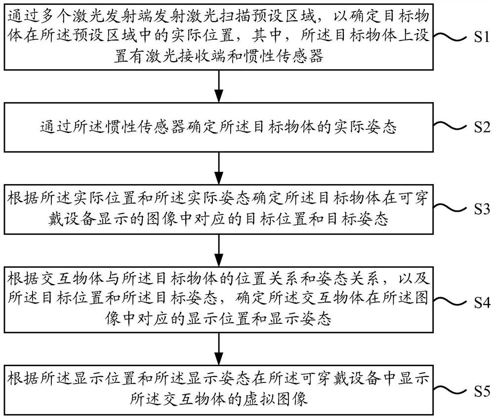
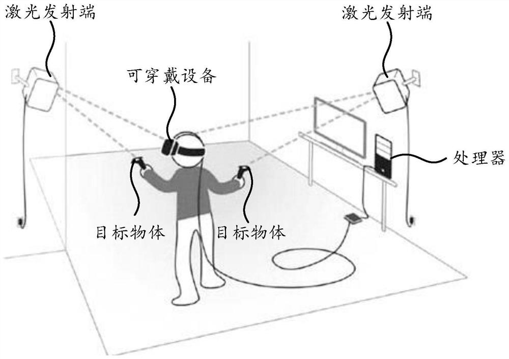
[0067] figure 1 It is a schematic flowchart of a virtual reality interaction method shown according to an embodiment of the present disclosure. The method shown in the embodiments of the present disclosure can be applied to a virtual reality interactive system, and the virtual reality interactive system includes multiple laser transmitters, laser receivers, inertial sensors and wearab...


PUM


Abstract

The invention relates to a virtual reality interaction method, which comprises the steps of transmitting laser through a plurality of laser transmitting ends to scan a preset area so as to determine an actual position of a target object in the preset area; determining the actual attitude of the target object through an inertial sensor; determining a target position and a target posture corresponding to the target object in the image displayed by a wearable device according to the actual position and the actual posture; determining the corresponding display position and display posture of the interactive object in the image according to the position relation and posture relation between the interactive object and the target object, the target position and the target posture; and displayingthe virtual image of the interactive object in the wearable device according to the display position and the display posture. According to the virtual reality interaction method, the actual position and the actual posture of the target object carried by the user can be determined in a larger range, so that the user can conveniently execute the action in the larger range, and the user can conveniently execute the action to interact with the wearable device.

Description

technical field [0001] The present disclosure relates to the field of display technology, and in particular, to a virtual reality interaction method, a virtual reality interaction device, electronic equipment, and a computer-readable storage medium. Background technique [0002] In related technologies, in order to realize the interaction between a virtual reality (Virtual Reality, VR) device and a wearer, the following methods are mainly adopted: [0003] 1. A touch panel is set on the virtual reality device. The user touches the touch panel to input a touch signal, and the virtual display device realizes corresponding functions according to the touch signal. [0004] However, when wearing a virtual reality device, the user generally covers the eyes completely for an immersive experience, so that the user touches the touch panel is a blind operation, which makes it difficult for the user to accurately determine the position of the touch panel. Moreover, the touch panel is ...

Claims


Application Information

Patent Timeline
IPC IPC(8): G06F3/0346G06F3/0487G06F1/16G06T7/70
CPCG06F3/0346G06F3/0487G06F1/163G06T7/70
Inventor 王冉冉周国栋杨宇
Owner HISENSE VISUAL TECH CO LTD
Learn More