Multi-channel temperature control device used for semiconductor coating equipment

A technology of coating equipment and temperature control device, which is applied in the direction of gaseous chemical plating, metal material coating process, coating, etc., can solve the problems of low equipment production capacity, long time consumption, and film failure, so as to improve efficiency and reduce cooling The effect of time required and effective success rate

Active Publication Date: 2020-10-13
浙江云度新材料科技有限公司
View PDF3 Cites 3 Cited by
  • Summary
  • Abstract
  • Description
  • Claims
  • Application Information

AI Technical Summary

Problems solved by technology

[0003] For semiconductor thin film deposition equipment, plasma will participate in the deposition reaction during the deposition process. Due to the release of plasma energy and the energy release of the reaction between chemical gases, the temperature of the heating plate and wafer will increase with the increase of radio frequency and process time. It will continue to rise; if the process is carried out at the same temperature, it is necessary to wait for the heating plate to drop to the same temperature before proceeding, which will consume a lot of time and the production capacity of the equipment is relatively low
If the temperature of the wafer and heating plate is raised too fast, the temperature of the wafer and heating plate will exceed the temperature that the film needs to withstand, causing the film to fail

Method used


Image

  • Multi-channel temperature control device used for semiconductor coating equipment
  • Multi-channel temperature control device used for semiconductor coating equipment
  • Multi-channel temperature control device used for semiconductor coating equipment

Examples


Embodiment 1

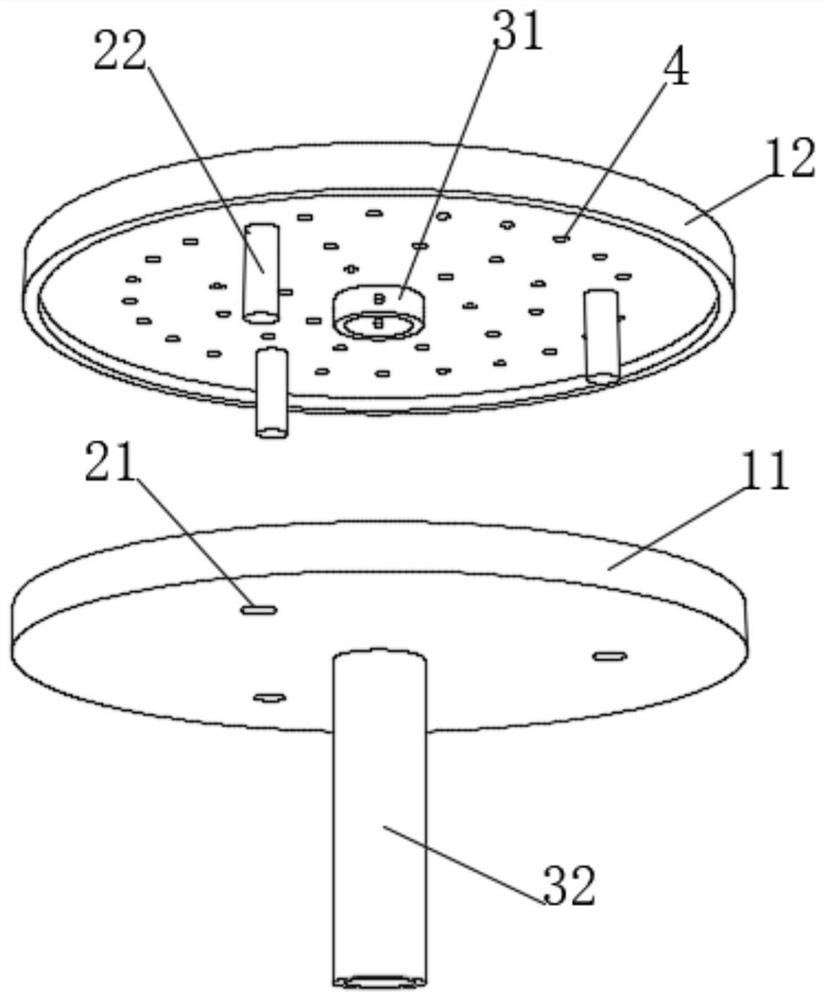
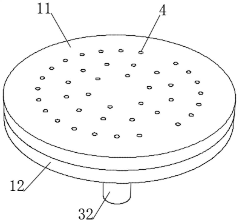
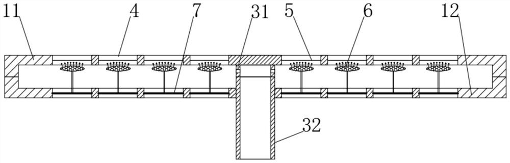
[0040] see Figure 1-2 , a multi-channel temperature control device for semiconductor coating equipment, including a matching upper heat conduction plate 11 and a lower heat conduction plate 12, a medium dispersion chamber is formed between the upper heat conduction plate 11 and the lower heat conduction plate 12, and the lower end of the lower heat conduction plate 12 A plurality of uniformly distributed ceramic rods 22 are fixedly connected, and a plurality of mounting holes 21 matching the ceramic rods 22 are drilled at the inner end of the upper heat conduction plate 11. The lower end of 12 is fixedly connected with an inner air diffuser channel 31 matching the upper end of the outer air diffuser channel 32, and the outer end of the inner air diffuser channel 31 is dug with a plurality of ventilation holes, which communicate with the medium dispersion chamber, and the upper heat conducting plate 11 and the lower The heat conduction plate 12 is dug with a plurality of corre...


PUM


Abstract

The invention discloses a multi-channel temperature control device used for semiconductor coating equipment, and belongs to the field of temperature control. According to the multi-channel temperaturecontrol device used for the semiconductor coating equipment, through the arrangement of a temperature control laminated channel layer and a selective heat conducting rod, when the temperature needs to be increased, heat conducting gas runs from bottom to top, an air blowing layer is attached to a fixed multi-channel plate, at the moment, part of the holes in the air blowing layer are blocked, theheat conduction gas enters the upper part of the temperature control device, the speed of the heat conduction gas to make contact with a semiconductor is decreased, and therefore the overall temperature rising speed of the temperature control device can be effectively controlled, the phenomenon that a film fails due to too high temperature rising of the semiconductor is avoided, and the success rate of semiconductor coating is effectively increased; and when the temperature needs to be decreased, the heat conduction gas moves downwards, so that the air blowing layer is bulged downwards untilthe air blowing layer is punctured by the selective heat conducting rod, and the heat conduction gas is directly contacted with the selective heat conducting rod to transfer heat downwards, so that the cooling speed is remarkably increased, the cooling time is shortened, and the semiconductor coating efficiency in the same time is effectively improved.

Description

technical field [0001] The invention relates to the field of temperature control, in particular to a multi-channel temperature control device for semiconductor coating equipment. Background technique [0002] Semiconductor equipment often needs to heat the wafer and the chamber or maintain the temperature required for the deposition reaction during the deposition reaction, so the heating plate must have a heating structure to meet the purpose of preheating the wafer. In order to solve the problem that the temperature of the heating plate rises too fast and cools down slowly during the process, the temperature of the heating plate is controlled by the cooling temperature control system to ensure that the temperature of the heating plate is stable during the process. In order to better control the temperature of the semiconductor, we need to transfer the temperature of the semiconductor to the heating plate, and control the temperature of the surface of the semiconductor by co...

Claims


Application Information

Patent Timeline
Patent Type & Authority Applications(China)
IPC IPC(8): C23C16/52C23C16/46
CPCC23C16/46C23C16/52
Inventor 李娟
Owner 浙江云度新材料科技有限公司
Why Eureka
Try Eureka