
Full-rotational-flow supersonic separation device

A separation device and supersonic technology, applied in swirl devices, devices whose axial direction of swirl remains unchanged, separation methods, etc., can solve the problem of inability to realize the free collocation of shrinkage section and diffuser section, narrow adaptability to working conditions, Difficult processing and other problems to achieve the effect of reducing the impact of re-evaporation of droplets, ensuring separation effect and separation efficiency, and easy processing

Active Publication Date: 2020-10-13
CHINA UNIV OF PETROLEUM (EAST CHINA)
View PDF6 Cites 3 Cited by
  • Summary
  • Abstract
  • Description
  • Claims
  • Application Information

AI Technical Summary

Problems solved by technology

[0013] (1) Difficult to process; (2) The constriction section and the diffuser section of the supersonic cyclone separation device are fixedly connected, so it is impossible to realize the free collocation of different types of constriction sections and diffuser sections, which makes the device's adaptability to working conditions wider. narrow

Method used


Image

  • Full-rotational-flow supersonic separation device
  • Full-rotational-flow supersonic separation device
  • Full-rotational-flow supersonic separation device

Examples


Embodiment Construction

[0059] Below in conjunction with accompanying drawing and specific embodiment the present invention is described in further detail:

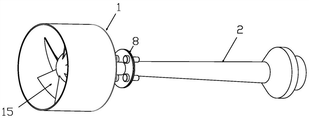
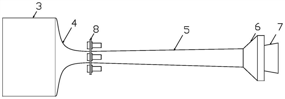
[0060] Such as figure 1 As shown, a full-swirl supersonic separation device includes a shell and a central swirl component. Among them, the shell includes a steady flow constriction section 1 and a diffuser separation section 2 connected in sequence, such as figure 2 shown.

[0061] definition figure 1 The left end is the front end of the separation device, and the steady flow contraction section 1 is located at the front side of the diffuser separation section 2.

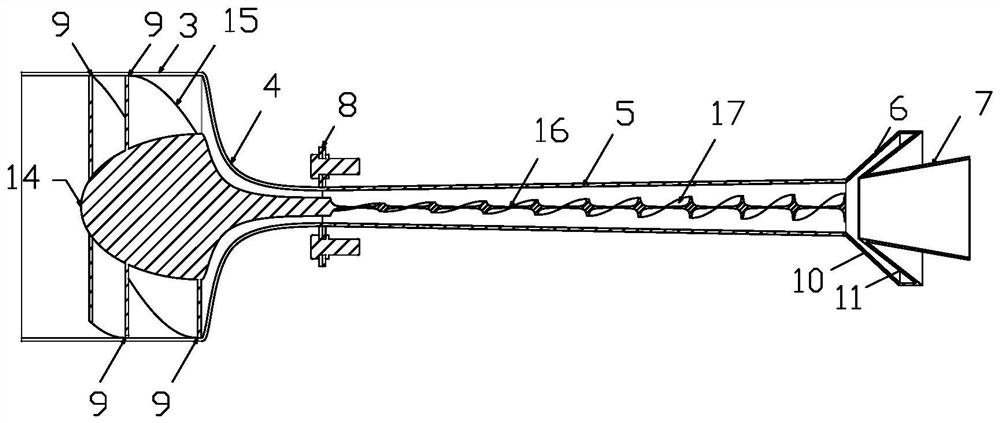
[0062] The central swirl part is located in the shell, that is, in the steady flow constriction section 1 and the diffuser separation section 2 .

[0063] The steady flow constriction section 1 includes a straight pipe steady flow section 3 and a Laval nozzle tapering section 4 .

[0064] The steady flow section 3 of the straight pipe is located at the front side of the taperin...


PUM


Abstract

The invention discloses a full-rotational-flow supersonic separation device. The full-rotational-flow supersonic separation device comprises a shell and a central rotational flow component. The shellcomprises a direct-current flow stabilizing section, a Laval spray pipe reducing section, a Laval spray pipe expanding section and the like. The central rotational flow component comprises a front central rotational flow component and a rear central rotational flow component. The front central rotational flow component is positioned in the direct-current flow stabilizing section and the Laval spray pipe reducing section, and the rear central rotational flow component is positioned in the Laval spray pipe expanding section. When gas enters the direct-current flow stabilizing section and the Laval spray pipe reducing section, gas flow expands in a rotational flow state and reaches supersonic speed after reaching the Laval spray pipe expanding section, the temperature and the pressure are further reduced, the gas begins to condense, and the process of condensing during rotational flow can effectively reduce the influence of re-evaporation of liquid drops. Besides, the rotational flow component is also arranged in the Laval spray pipe expanding section, the rotational flow capacity of the rotational flow component is high and durable, and the separation effect and the separation efficiency of the device are guaranteed.

Description

technical field [0001] The invention belongs to the technical field of low-temperature condensation and cyclone separation, and in particular relates to a full-swirl supersonic separation device, which is especially suitable for low-temperature condensation and cyclone separation of impurity components such as water vapor, acid gas, and heavy hydrocarbons in natural gas. Background technique [0002] In the field of natural gas exploitation, the currently extracted natural gas is often saturated with water vapor and contains some heavy hydrocarbon components. In order to meet the requirements of natural gas export and use, water vapor, acid gas and heavy hydrocarbon components must be separated. [0003] Traditional natural gas separation processes include cooling method, chemical absorption method, adsorption method and membrane separation method. However, these separation processes have various disadvantages in the natural gas separation process, and it is urgent to propos...

Claims


Application Information

Patent Timeline
IPC IPC(8): C10L3/10B01D45/14B01D5/00
CPCC10L3/101C10L3/102C10L3/106B01D45/14B01D5/0057B01D45/16B04C3/00B04C3/02B04C3/06B04C2003/006B01D53/002B01D53/265B01D2256/245B01D2257/702B01D53/24B01D5/0033B01D5/009C10L2290/34C10L2290/54C10L2290/56
Inventor 边江曹学文李钰璇谢振强郭丹刘杨
Owner CHINA UNIV OF PETROLEUM (EAST CHINA)
Learn More