
Intelligent high-end digitization die production equipment

A kind of production equipment and high-end technology, which is applied in the direction of metal processing equipment, perforating tools, forming tools, etc., can solve the problems of inconvenient, time-consuming and laborious, and low efficiency in the process of unloading and retrieving processed parts, and achieve convenient loading and unloading. The effect of taking material, avoiding splashing and improving processing efficiency

Pending Publication Date: 2020-10-13
杜元*
View PDF7 Cites 1 Cited by
  • Summary
  • Abstract
  • Description
  • Claims
  • Application Information

AI Technical Summary

Problems solved by technology

[0002] The digital production of molds has become a new development trend. Before the production of molds, it is necessary to punch the raw material plates used in the production of molds, so as to facilitate the production of molds. Traditional equipment needs to manually move the plates to achieve multiple positions of the punching head on the plates. Punching is time-consuming, labor-intensive, inefficient, and manual operation is more dangerous
[0003] The Chinese patent with the notification number CN108655764A discloses a high-end digital mold production equipment. When the equipment is in the initial state, the driving motor, sliding motor, drive-rotating motor, conveyor, high-speed motor, rotating motor, and The motor and the telescopic cylinder are in a stop working state, so that the above structure is in the initial position in the initial state, and can be adjusted in the follow-up work to effectively improve the work coordination of the equipment; but the equipment is not equipped with a lifting mechanism, which causes the workpiece to be discharged and the process of retrieving is inconvenient

Method used


Image

  • Intelligent high-end digitization die production equipment
  • Intelligent high-end digitization die production equipment
  • Intelligent high-end digitization die production equipment

Examples


Embodiment Construction

[0038]The technical solutions of the present invention will be clearly and completely described below in conjunction with the embodiments. Apparently, the described embodiments are only some of the embodiments of the present invention, not all of them. Based on the embodiments of the present invention, all other embodiments obtained by persons of ordinary skill in the art without creative efforts fall within the protection scope of the present invention.

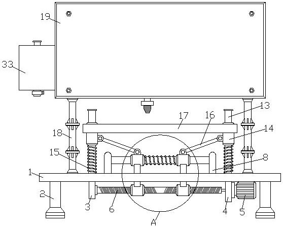
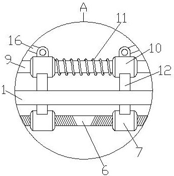
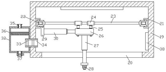
[0039] like Figure 1-6 As shown, an intelligent high-end digital mold production equipment includes a workbench 1 and four bases 2 installed on the bottom surface of the installation platform, the bottom of the base 2 is connected to the ground, and a card slot is opened between the top surface and the bottom surface of the workbench 1 42, the inner wall of the card slot 42 is movably connected with the outer surface of the fixed rod 12, and the card slot 42 is used to limit the fixed rod 12 to ensure that the fixed rod 12 ...


PUM


Abstract

The invention discloses intelligent high-end digitization die production equipment. The die production equipment comprises a workbench and four bases installed on the bottom surface of the installation workbench, wherein the bottoms of the bases are connected with the ground; two symmetrical straight plates are fixedly installed on the top of the workbench; a sliding rod is fixedly installed between the side surfaces, close to each other , of the two straight plates; two symmetrical sliding sleeves are movably connected to the outer surface of the sliding rod; a first spring is fixedly installed between one ends, close to each other, of the two sliding sleeves; two symmetrical connecting columns are fixedly installed at the top of the workbench; movable sleeves are movably connected to theouter surfaces of the connecting columns; and second springs are fixedly installed between the bottoms of the movable sleeves and the top surface of the workbench. According to the intelligent high-end digitization die production equipment, the position of a mounting plate on an XY axis coordinate system can be controlled and adjusted, so that a plurality of punching positions of the plate are punched without manually adjusting the plate, the operation is simple and convenient, and the machining efficiency of the equipment is improved.

Description

technical field [0001] The invention belongs to the field of mold production and relates to digital processing technology, in particular to intelligent high-end digital mold production equipment. Background technique [0002] The digital production of molds has become a new development trend. Before the production of molds, it is necessary to punch the raw material plates used in the production of molds, so as to facilitate the production of molds. Traditional equipment needs to manually move the plates to achieve multiple positions of the punching head on the plates. Punching is time-consuming, labor-intensive, inefficient, and manual operation is dangerous. [0003] The Chinese patent with the notification number CN108655764A discloses a high-end digital mold production equipment. When the equipment is in the initial state, the driving motor, sliding motor, drive-rotating motor, conveyor, high-speed motor, rotating motor, and The motor and the telescopic cylinder are in a...

Claims


Application Information

Patent Timeline
Patent Type & Authority Applications(China)
IPC IPC(8): B21D28/26B21D28/34B21D37/00B21D37/16B21D43/02
CPCB21D28/26B21D28/34B21D37/00B21D37/16B21D43/02
Inventor 杜元
Owner 杜元*
Learn More