
Coating mold head with cavity pressure adjusted in a horizontal direction

A technology that adjusts the cavity in a horizontal direction and is applied in the direction of devices and coatings that apply liquid to the surface. It can solve the problems that the cavity pressure of the storage cavity cannot be adjusted flexibly, and the coating cannot be completely solved, and achieves good lateral thickness consistency. , Good density uniformity, improve the effect of density uniformity

Pending Publication Date: 2020-10-13
HUIZHOU YINGHE TECH
View PDF0 Cites 9 Cited by
  • Summary
  • Abstract
  • Description
  • Claims
  • Application Information

AI Technical Summary

Problems solved by technology

[0003] However, in the current coating die head, since the cavity pressure is fixed after the shape and size of the storage cavity are determined, the cavity pressure of the storage cavity cannot be adjusted flexibly, and the coating cannot be adjusted through the flexible adjustment of the cavity pressure of the storage cavity. The flow rate and flow rate of the slurry, and only through the adjustment of the coating port gap can not completely solve the coating problem

Method used


Image

  • Coating mold head with cavity pressure adjusted in a horizontal direction
  • Coating mold head with cavity pressure adjusted in a horizontal direction
  • Coating mold head with cavity pressure adjusted in a horizontal direction

Examples


Embodiment Construction

[0032] The technical solutions of the present invention will be described in further detail below in conjunction with specific embodiments and accompanying drawings, but the protection scope and implementation methods of the present invention are not limited thereto. In the description of specific embodiments, it should be noted that the orientations or positional relationships indicated by the terms "upper", "lower", "front", "back", "left", "right" etc. are based on those shown in the accompanying drawings. Orientation or positional relationship, or the orientation or positional relationship that the invention product is usually placed in use, is only used to distinguish the description, and is only for the convenience of describing the present invention and simplifying the description, rather than indicating or implying that the structure or element referred to must have Specific orientations, constructions, and operations in specific orientations should therefore not be con...


PUM


Abstract

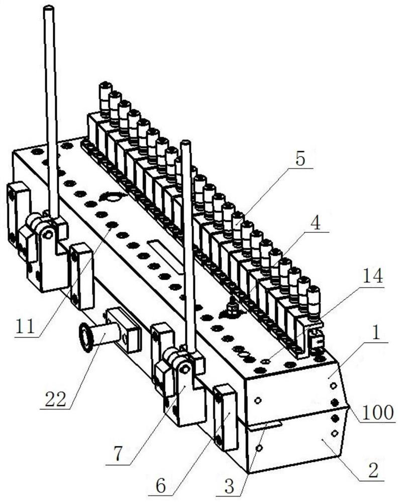
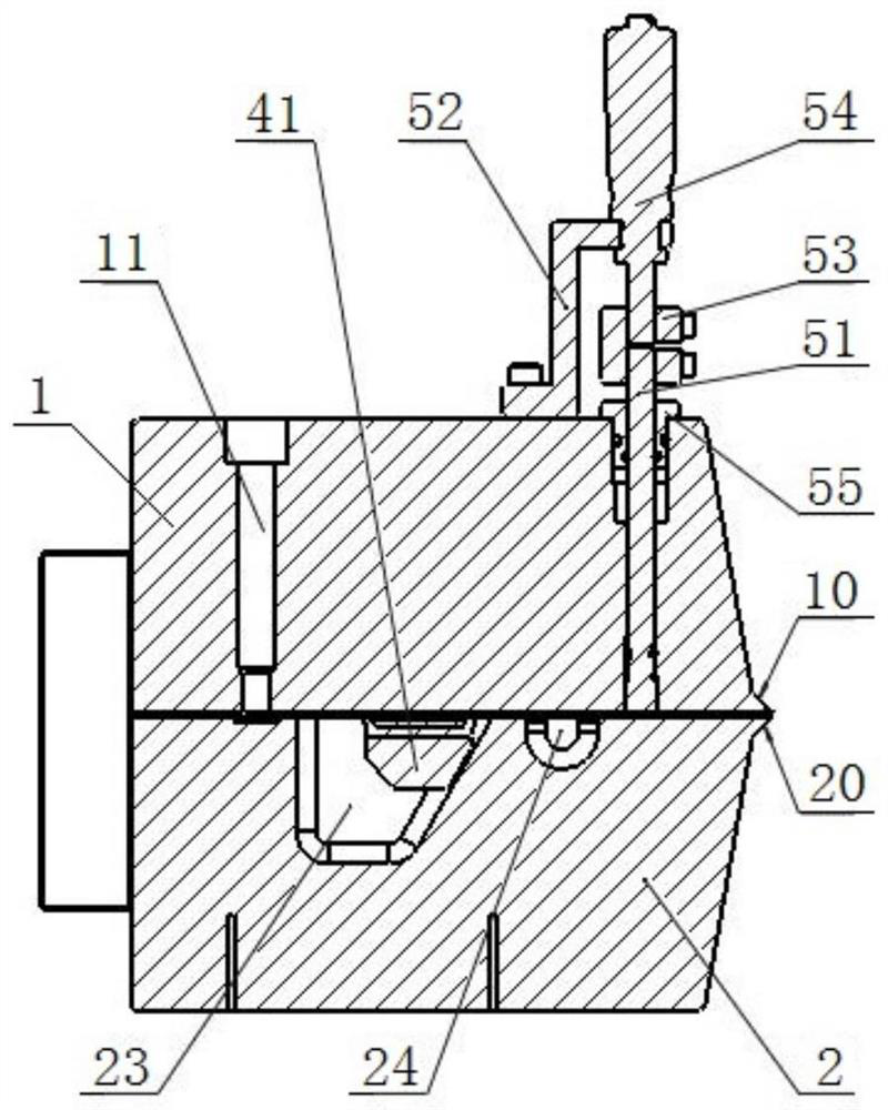
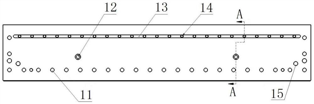
The invention discloses a coating mold head with cavity pressure adjusted in a horizontal direction. The coating mold head includes an upper mold head and a lower mold head, a slit coating opening isformed in a front end clipper seam between the upper mold head and the lower mold head, a storing cavity is opened in the lower mold head, the storing cavity communicates with the slit coating opening, a cavity pressure adjustment mechanism is arranged on the upper mold head, and the cavity pressure adjustment mechanism includes a sliding block located in the storing cavity, and a transmission adjustment rod used to make a cam head be connected with the sliding block in a transmission mode. When the transmission adjustment rod rotates, the cam head can drive the sliding block to move in a horizontal direction of coating feeding to adjust the cavity pressure in the storing cavity. The coating mold head is provided with the cavity pressure adjustment mechanism, the cavity pressure in the storing cavity can be flexibly adjusted in real-time in the production process of coating, so that the flow velocity and flow of coating slurry can be adjusted, the coating mold head is provided with a gap adjustment mechanism coordinately, and the real-time adjustment of the flow velocity and flow of the coating slurry can be effectively finished in the production process of the coating.

Description

technical field [0001] The invention relates to the technical field of coating equipment, in particular to a coating die head capable of adjusting cavity pressure in a horizontal direction. Background technique [0002] During the production of lithium battery pole pieces, it is necessary to coat the slurry on the pole piece substrate. The surface density uniformity, transverse thickness consistency and accuracy of the coated coating are mainly determined by the slurry flow rate and flow rate before coating, while the flow rate and flow rate of the slurry are mainly determined by the cavity pressure of the material storage chamber and the gap between the coating ports. [0003] However, in the current coating die head, since the cavity pressure is fixed after the shape and size of the storage cavity are determined, the cavity pressure of the storage cavity cannot be adjusted flexibly, and the coating cannot be adjusted through the flexible adjustment of the cavity pressure o...

Claims


Application Information

Patent Timeline
Patent Type & Authority Applications(China)
IPC IPC(8): B05C5/02
CPCB05C5/0258
Inventor 江正贤曹稚英李少杰阮丹琳
Owner HUIZHOU YINGHE TECH
Learn More