Pressure swing adsorption method for separating hydrogen, nitrogen and pure carbon dioxide from transformation gas
A pressure swing adsorption method and a gas shift technology, which is applied in the field of pressure swing adsorption and can solve the problems of easy nitrogen loss, equipment investment and energy consumption increase.
- Summary
- Abstract
- Description
- Claims
- Application Information
AI Technical Summary
Problems solved by technology
Method used
Image


Examples
Embodiment 1
[0042] Coal is used as raw material, and the shift gas of coal gas produced by introducing air during the gas production process is used as raw material gas to separate pure CO 2 And hydrogen, nitrogen product gas.
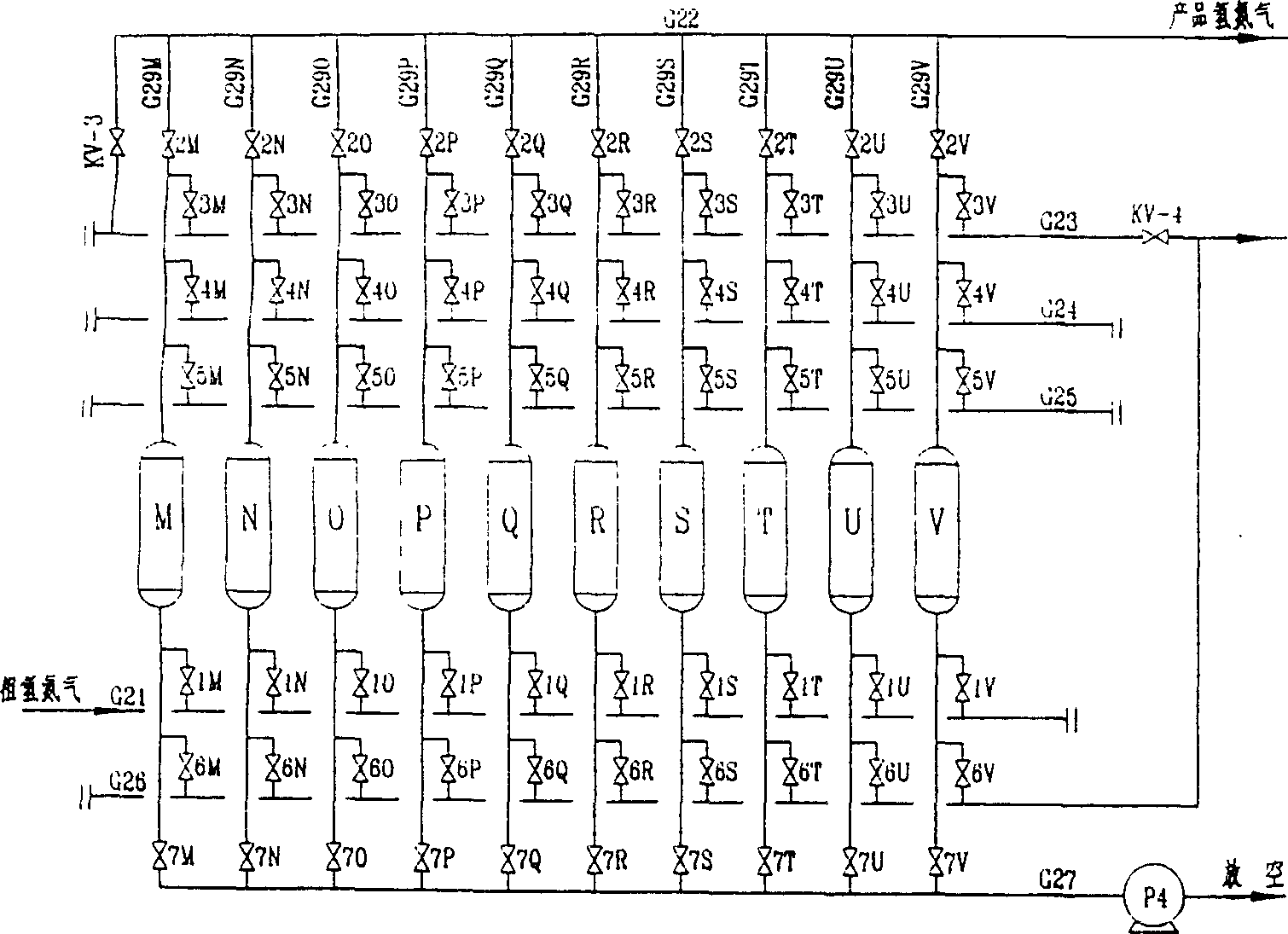
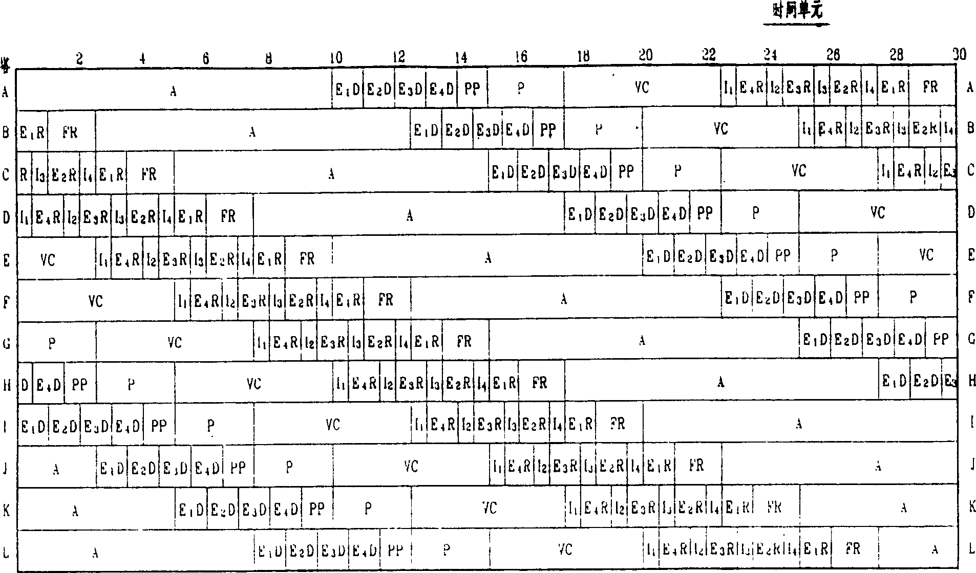
[0043] figure 1 , figure 2 For the technological process of this embodiment, image 3 , Figure 4 It is the operating program table of the present embodiment.
[0044] Typical composition of shift gas using coal as raw material: component CO 2 CO H 2 N 2 CH 4 h 2 S H 2 O concentration V% 25-30 0.3-3 45-55 18-22 1-2 <150PRm Saturation temperature 25-40℃ Pressure 0.6~0.8MPa
[0045] figure 1 and figure 2 The process flow charts of two groups of adsorption towers are respectively, figure 1 for the first group, figure 2 For the second group, the two groups operate in series, and the first group is to convert the CO in the gas 2 Purify to more than 98%, meet the requirements of synthetic urea, the second group function is to purify part ...
Embodiment 2
[0120] Fig. 5 is a process flow chart of the present embodiment, and Fig. 6 is a process table of the process steps of the present embodiment. In this implementation, there are two groups of adsorption towers in group A and group B, group A has six adsorption towers A1-A6, and group B has six adsorption towers B1-B6. Group A and Group B operate in series, and Group A is used to purify CO 2 , Group B is used to remove crude hydrogen and CO in nitrogen 2 . The difference from Embodiment 1 is that in this embodiment, each column in group A is operated in series with a corresponding column in group B.
[0121] The shift gas pressure, composition, and temperature used in this example are the same as those in Example 1.
[0122] The adsorbents filled in the adsorption towers of group A are three kinds of adsorbents: activated alumina, activated carbon and silica gel, which form a combined bed from bottom to top in turn, and silica gel adsorbents are filled in the adsorption tower...
Embodiment 3
[0165] Other conditions are the same as in Example 1, except that crude hydrogen and ammonia are pressurized to 1.8Mpa and enter the second group of adsorption towers. Because the second group of pressure increases, the volume of the second group of adsorption towers is reduced to that of the first group. two thirds. The result of the operation is CO 2 Purity 99.5(V), yield greater than 70%, CO in hydrogen and nitrogen 2 Less than 0.2% (V), hydrogen yield 98.5%, nitrogen yield 94%.
PUM
 Abstract
Description
Claims
Application Information
 - R&D
- Intellectual Property
- Life Sciences
- Materials
- Tech Scout
- Unparalleled Data Quality
- Higher Quality Content
- 60% Fewer Hallucinations
Browse by: Latest US Patents, China's latest patents, Technical Efficacy Thesaurus, Application Domain, Technology Topic, Popular Technical Reports.
© 2025 PatSnap. All rights reserved.Legal|Privacy policy|Modern Slavery Act Transparency Statement|Sitemap|About US| Contact US: help@patsnap.com