
Patsnap Eureka
For R&D, Patsnap Eureka makes reading and utilizing patents & technical documents easy.
Patsnap Eureka AIR
Designed for self-driven R&D workflows. Generate viable solutions, solve complex R&D challenges, empower your innovation with AI.

Patsnap Eureka Materials
Designed for material experts only. Revolutionize your material R&D, from search, analyze, to developing new materials.

TechResearch
Generate reliable direction feasibility study reports for your R&D in just a few steps.

TechSeek
Discover and master advanced knowledge NOW. Basics, ideas, possibilities, all at once.

TechMind
As an expert in R&D Theories, TechMind can generates customized viable solutions instantly.

TechRisk
Analyze your overall solution with one click, know your potential R&D risks in advance.

TechMonitor
Get weekly tech updates, stay abreast of the latest tech innovations and key insights.
A square wood block cutting device
A technology for cutting devices and wood blocks, which is applied in feeding devices, sawing components, sawing equipment, etc., and can solve problems such as different widths, potential safety hazards, and waste of wood
- Summary
- Abstract
- Description
- Claims
- Application Information
AI Technical Summary
Problems solved by technology
Method used
Image

Examples
Embodiment 1
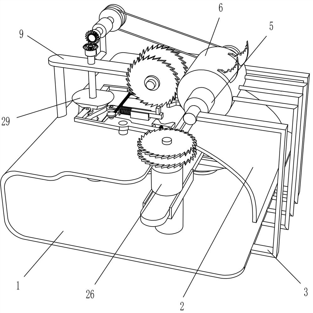
[0026] A square wood block cutting device such as figure 1 and figure 2 As shown, it includes base plate 1, slide plate 2, transmission mechanism, first pulley 8, slitting mechanism, power shaft 10, bevel gear 11, first transmission shaft 14, second pulley 15, first belt 16, horizontal The cutting mechanism and the clamping mechanism, the upper right part of the base plate 1 is fixedly connected with the slide plate 2, the transmission mechanism is installed on the lower layer of the base plate 1, the first pulley 8 is fixedly connected to the transmission mechanism, the longitudinal cutting mechanism is installed on the upper layer of the base plate 1, and the bottom plate The left part of 1 is rotatably provided with a power shaft 10, the power shaft 10 is movably mounted on the upper layer of the bottom plate 1, and the slitting mechanism is rotatably connected with a first transmission shaft 14, and the front end of the first transmission shaft 14 is connected to the top ...
Embodiment 2
[0031] On the basis of Example 1, such as image 3 and Figure 4 As shown, the slitting mechanism includes a support plate 9, a power motor 12 and a first cutting wheel 13, the support plate 9 is fixedly connected to the upper left part of the bottom plate 1, and the first transmission shaft 14 is rotatably arranged at the middle part of the rear side of the support plate 9 , the power motor 12 is affixed to the right end of the support plate 9 , and the first cutting wheel 13 is symmetrically affixed to the output shafts on both sides of the power motor 12 .
[0032] The cross-cutting mechanism includes a third pulley 17, a first rotating rod 18, a fourth pulley 181, a second belt 19, a turntable 20, a straight plate 21, a base 22, a guide rail 23, a first slide bar 24, and a transmission motor 25. The second transmission shaft 26 and the second cutting wheel 27, the lower part of the power shaft 10 is fixedly connected with the third pulley 17, the first rotating rod 18 is ...
Embodiment 3
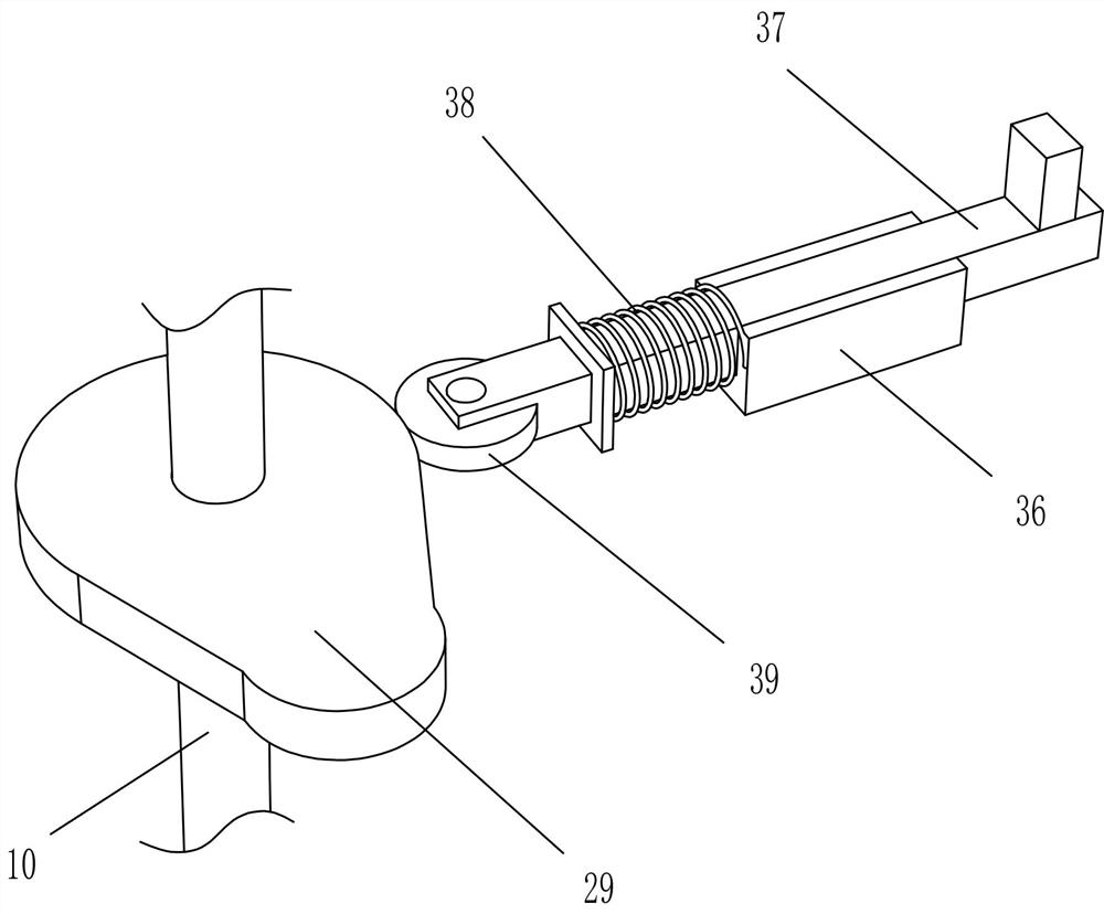
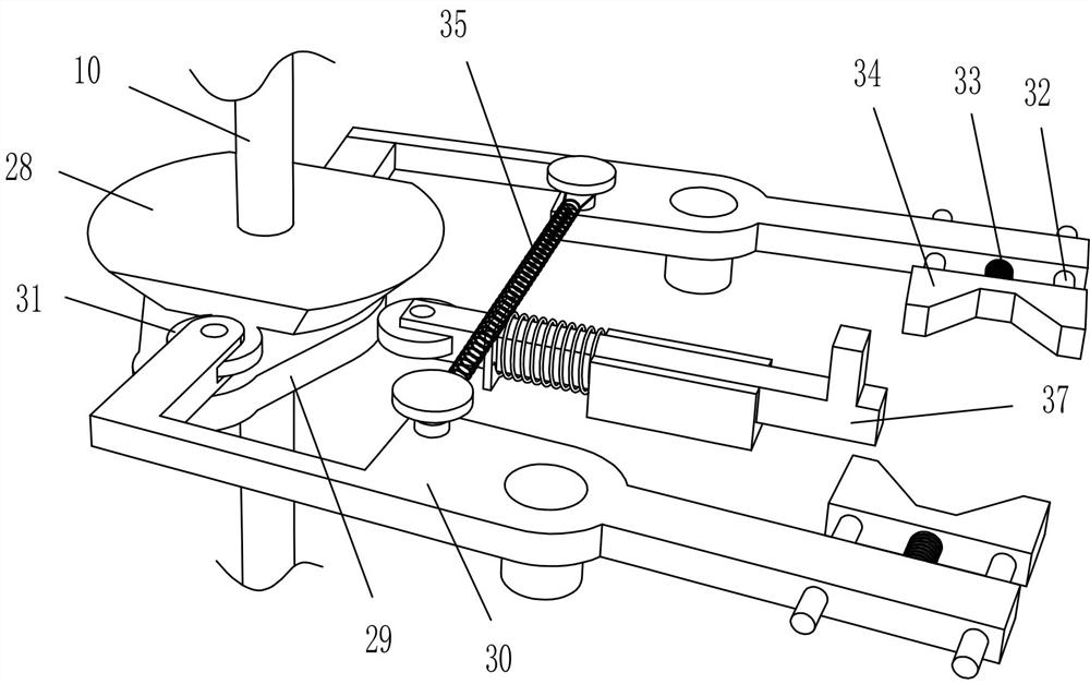
[0036] On the basis of Example 2, such as Figure 5 and Image 6 As shown, the clamping mechanism includes a cam 28, an extrusion cam 29, a second rotating rod 30, a first pulley 31, a movable rod 32, a compression spring 33, an extruding block 34, a telescopic spring 35, a guide sleeve 36, a first Two slide bars 37, back-moving spring 38 and second pulley 39, cam one 28 and extruding cam 29 are all fixedly connected in the middle part of power shaft 10, extruding cam 29 is positioned at cam one 28 below, base plate 1 upper layer top forward and backward symmetrical rotation connection There is a second rotating rod 30, symmetrically located on the front and rear sides of cam one 28 and in contact with it, the first pulley 31 is rotated and installed on the left end of the second rotating rod 30, and the right part of the second rotating rod 30 is slidingly connected with two movable rods 32. A squeeze block 34 is connected between the inner ends of the movable rods 32 on the...
PUM
 Abstract
Description
Claims
Application Information
 - R&D Engineer
- R&D Manager
- IP Professional
- Industry Leading Data Capabilities
- Powerful AI technology
- Patent DNA Extraction
Browse by: Latest US Patents, China's latest patents, Technical Efficacy Thesaurus, Application Domain, Technology Topic, Popular Technical Reports.
© 2024 PatSnap. All rights reserved.Legal|Privacy policy|Modern Slavery Act Transparency Statement|Sitemap|About US| Contact US: help@patsnap.com