
Rolling force detection structure of rolling mill

A technology for detecting structure and rolling force, applied in metal rolling, metal rolling, length measuring devices, etc., can solve problems such as inability to compensate contact surface wear, wear of wear-resistant plate of roll changing trolley, and aggravated wear of roll changing mechanism, etc. , to achieve the effect of avoiding layer-by-layer superposition structure, reducing contact surface, reducing workload and difficulty

Active Publication Date: 2021-11-23
NINGBO IRON & STEEL
View PDF12 Cites 0 Cited by
  • Summary
  • Abstract
  • Description
  • Claims
  • Application Information

AI Technical Summary

Problems solved by technology

The wear of the wear plate will affect the measurement accuracy. The wear plate of the roll changing trolley is worn and needs to be replaced regularly, which requires a lot of maintenance.
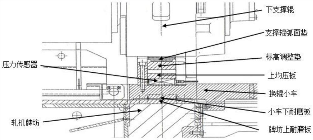
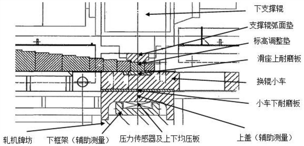
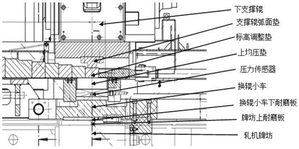
[0008] The rolling force detection of the existing device, the rolling force transmission process, must be transmitted through the roll change mechanism of the lower back-up roll. system is about 220 tons), with the continuous replacement of support rolls during the use of the device, the wear of the roll change mechanism will increase, and the wear between the contact surfaces cannot be compensated, resulting in changes in the horizontality and elevation of the pressure sensor, resulting in the rolling force measurement the accuracy of

Method used


Image

  • Rolling force detection structure of rolling mill
  • Rolling force detection structure of rolling mill
  • Rolling force detection structure of rolling mill

Examples


Embodiment Construction

[0024] Below in conjunction with specific embodiment, further illustrate the present invention. It should be understood that these examples are only used to illustrate the present invention and are not intended to limit the scope of the present invention. In addition, it should be understood that after reading the teachings of the present invention, those skilled in the art can make various changes or modifications to the present invention, and these equivalent forms also fall within the scope defined by the appended claims of the present application.

[0025] Such as Figure 4 The rolling force detection structure of a rolling mill shown includes a pressure equalizing plate 1 , a pressure sensor 2 , a compensation backing plate 3 and a roll changing trolley 4 .

[0026] The pressure equalizing plate 1, the pressure sensor 2 and the compensation backing plate 3 are stacked and fixed in sequence to form an integral pressure sensing unit. The pressure equalizing plate 1 and the...


PUM


Abstract

The invention relates to a rolling force detection structure of a rolling mill, which comprises a pressure equalizing plate, a pressure sensor, a compensation backing plate and a roll changing trolley. There is a through slot along the vertical direction, the pressure sensing unit is set inside the slot and the bottom is supported by the rolling mill archway, the pressure sensing unit is limited by the roll changing trolley and can move with the roll changing trolley. The present invention gets rid of the dependence of the rolling force transmission process on the roll changing mechanism of the rolling mill and other auxiliary measurement systems, and avoids the layer-by-layer superposition structure of the roll changing system and other auxiliary measurement systems, the cumulative deviation of machining accuracy, and the wear and tear between parts on the accuracy of rolling force detection To improve the reliability and accuracy of the rolling force detection of the rolling mill.

Description

technical field [0001] The invention belongs to the technical field of rolling force detection of a rolling mill, and in particular relates to a rolling force detection structure of a rolling mill. Background technique [0002] Steel rolling mill is an important equipment for processing plates / strips. Plates / strips are high value-added steel products. The accuracy of steel products mainly refers to the accuracy of external dimensions. Accuracy indicators such as degrees. Among all the precision indicators, the flatness accuracy is one of the most important quality indicators to measure the sheet / strip, and it is an essential control method to calculate the flatness accuracy by using the measured value of the rolling force detection system. [0003] At present, the rolling force detection system adopted by the rolling mill usually adopts the pressure sensor products of George Keck Company of Canada or ABB Company of Sweden. The sensor is installed under the bearing seat of ...

Claims


Application Information

Patent Timeline
Patent Type & Authority Patents(China)
IPC IPC(8): B21B38/08
CPCB21B38/08
Inventor 张保忠韩建国宋志东陈国强刘光远陈红兵
Owner NINGBO IRON & STEEL
Learn More