Gas flow standard device with high and low pressure double calibration sections, and calibration method thereof

A gas flow, standard device technology, applied in test/calibration devices, measurement devices, liquid/fluid solid measurement, etc., can solve the problems of high cost and narrow calibration range, reduce construction costs, improve calibration accuracy, expand The effect of calibration capability

Pending Publication Date: 2020-10-02
AVIC SHENYANG AERODYNAMICS RES INST
View PDF3 Cites 6 Cited by
  • Summary
  • Abstract
  • Description
  • Claims
  • Application Information

AI Technical Summary

Problems solved by technology

[0004] The present invention aims at the defects that the existing flowmeters can only be calibrated under positive pressure conditions, the calibration range is narrow, and the cost is high, and provides a high-calibration flowmeter that can improve the calibration ability, expand the calibration range, have low cost, and can meet special calibration requirements. Flow standard device and calibration method of low pressure double calibration section

Method used


Image

  • Gas flow standard device with high and low pressure double calibration sections, and calibration method thereof
  • Gas flow standard device with high and low pressure double calibration sections, and calibration method thereof
  • Gas flow standard device with high and low pressure double calibration sections, and calibration method thereof

Examples


Embodiment 1

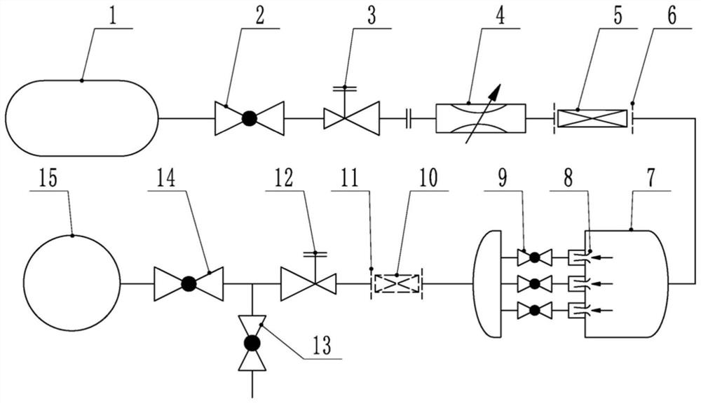
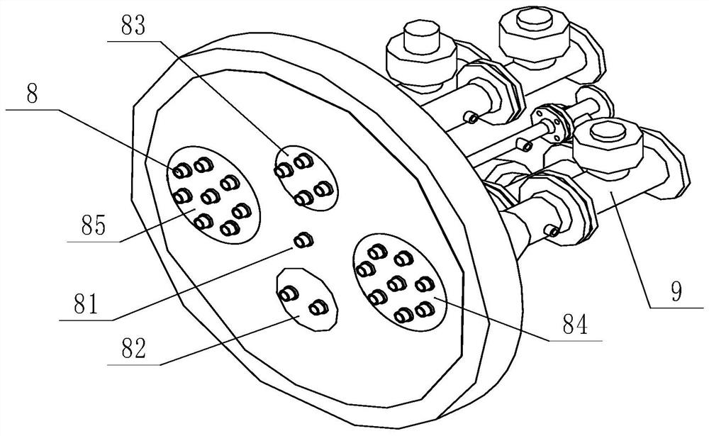
[0044] Combine figure 1 , figure 2 , image 3 , Figure 4 with Figure 5 This embodiment will be described. In this embodiment, a gas flow standard device with high and low pressure dual calibration sections involved in this embodiment includes a high-pressure gas source 1, a high-pressure stop valve 2, a high-pressure regulating valve 3, and an adjustable Flow valve 4, high pressure calibrated flow meter 5, high pressure calibration section 6, stagnation vessel 7, critical flow sonic nozzle standard table 8, branch stop valve 9, low pressure calibrated flow meter 10, low pressure calibration section 11, low pressure regulating valve 12. Low-pressure exhaust valve 13, low-pressure shut-off valve 14, and vacuum source 15, the outlet of said high-pressure gas source 1 and high-pressure shut-off valve 2, high-pressure regulating valve 3, adjustable flow valve 4, high-pressure calibration section 6, stagnation The container 7, the low pressure calibration section 11, the low pressu...

Embodiment 2

[0049] This embodiment will be described in conjunction with Embodiment 1. In this embodiment, the calibration method of a gas flow standard device with high and low pressure dual calibration sections involved in this embodiment includes the following steps:

[0050] Step 1. Use the high pressure calibrated flow meter 5 to calibrate the critical state high pressure flow meter;

[0051] Step 2: Use the high-pressure calibrated flowmeter 5 to calibrate the non-critical state high-pressure flowmeter;

[0052] Step 3: Use the low-pressure calibrated flowmeter 10 to calibrate the low-pressure flowmeter.

[0053] A gas flow standard device and calibration method with high and low pressure dual calibration sections, which can be used for the calibration and verification of high-pressure working condition flowmeters and low-pressure working condition flowmeters. The total mass flow flowing through the standard meter can be passed through the following formula Calculation:

[0054]

[0055] Whe...

Embodiment 3

[0065] This embodiment will be described in conjunction with embodiment 1 and embodiment 2.

[0066] 1) When calibrating the critical state high pressure flow meter, the high pressure to be calibrated flow meter 5 is between the adjustable flow valve 4 and the stagnation vessel 7, and the actual state is similar Image 6 , The calibrated flow meter is located at section A2, the adjustable flow valve 4 is located at section A1, and the stagnation container 7 is the space in front of section A3. At this time P01> P02> P03, A1 k1, P01 / P03> k2, k1 and k2 are all a value greater than 1. The pipeline state set according to this area, as long as P01 is high enough, the calibrated flowmeter at section 2 can reach the critical state, that is, the throat reaches the speed of sound. That is to provide the ability to calibrate critical flow meters.

[0067] 2) When calibrating a non-critical state high pressure flow meter, the high pressure to be calibrated flow meter 5 is between the high pre...


PUM


Abstract

The invention discloses a gas flow standard device with high and low pressure double calibration sections, and a calibration method thereof, and belongs to the field of gas flow metering calibration and verification. The flow standard device with the high and low pressure double calibration sections, and the calibration method thereof are provided in order to overcome the defects that an existingflow meter can only be calibrated under the positive pressure working condition and is narrow in calibration range and high in cost. In the invention, an outlet of a high-pressure gas source is sequentially communicated with a high-pressure stop valve, a high-pressure regulating valve, an adjustable throttle valve, a high-pressure calibration section, a stagnation container, a low-pressure calibration section, a low-pressure regulating valve, a low-pressure stop valve and a vacuum gas source, and a high-pressure calibrated flow meter is arranged in the high-pressure calibration section; and acritical flow sonic nozzle standard meter and a branch stop valve are arranged in the stagnation container, a low-pressure calibrated flow meter is arranged in the low-pressure calibration section, and the critical state high-pressure flow meter, the non-critical state high-pressure flow meter and the low-pressure flow meter are calibrated by adjusting the high-pressure calibrated flow meter and the low-pressure calibrated flow meter. The gas flow calibration device and method are mainly used for calibrating and detecting the gas flow.

Description

Technical field [0001] The invention belongs to the field of gas flow measurement calibration and verification, and specifically relates to a flow standard device and a calibration method for a critical flow nozzle providing high and low pressure dual calibration sections. Background technique [0002] Accurate measurement of gas flow has a wide range of needs in the fields of petroleum, natural gas, chemical industry, energy saving, environmental protection, aerospace and so on. Some flowmeters have a wide range of working conditions, such as the same mass flow rate, they may work at different stagnation pressures. The conventional negative pressure method or positive pressure method gas flow calibration device cannot fully meet the calibration requirements of some flowmeters in terms of calibration flow capacity range, calibration accuracy, and calibration working condition range. The utility model patent with publication number CN104501917A published a super-large-diameter so...

Claims


Application Information

Patent Timeline
IPC IPC(8): G01F25/00
CPCG01F25/00G01F25/15
Inventor 曹永飞马晓光郭大鹏宋孝宇
Owner AVIC SHENYANG AERODYNAMICS RES INST
Why Eureka
Try Eureka