Pressure reducing and stabilizing valve

A pressure-stabilizing valve and spool technology, applied in the field of decompression and pressure-stabilizing valves, can solve the problem that the fire extinguishing agent is difficult to penetrate, and achieve the effects of increasing the range of protection, increasing the delivery distance, and increasing the storage pressure

Pending Publication Date: 2020-10-02
浙江蓝盾电工新材料科技有限公司 +1
View PDF0 Cites 0 Cited by
  • Summary
  • Abstract
  • Description
  • Claims
  • Application Information

AI Technical Summary

Problems solved by technology

[0002] With the frequent occurrence of electrical fires, the disadvantages of the traditional gas fire extinguishing system for electrical fires are becoming more and more obvious. For electrical fires, especially fires in electrical cabinets, it is difficult for the fire extinguishing agent to penetrate through the distribution of the traditional gas fire extinguishing system. The shell of the electrical cabinet, enter the electrical cabinet to extinguish the fire
[0003] In order to improve the fire extinguishing efficiency, most of the schemes adopted now are to extend the fire detection tube to the inside of the power distribution cabinet, and the fire extinguishing agent is transported to the inside of the electrical cabinet through the fire detection tube. In order to meet the requirement of blasting temperature, the plastic material tube needs to ensure its wall thickness and relatively stable pressure inside the tube, while the fire detection tube device needs to increase the storage pressure of fire extinguishing agent to meet the requirement of spraying in order to meet the requirement of delivery distance. contradictory issue

Method used


Image

  • Pressure reducing and stabilizing valve
  • Pressure reducing and stabilizing valve
  • Pressure reducing and stabilizing valve

Examples


Embodiment Construction

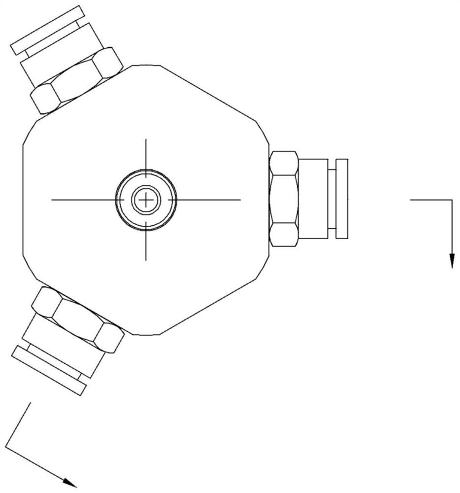
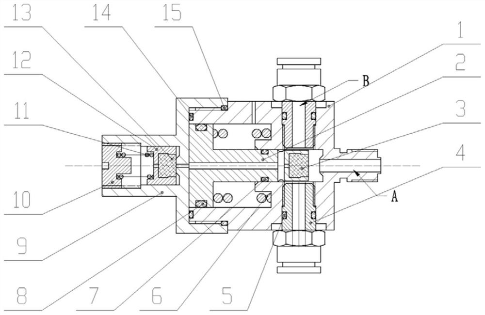
[0019] Such as figure 1 , 2 A pressure reducing and stabilizing valve shown in 3, a pressure reducing and stabilizing valve, comprising a valve body 1, a valve core 2 installed inside the valve body, a first end face gasket 3 is arranged in the valve body at the upper end of the valve core , the two sides of the first end face gasket 3 are provided with hose joints 4, the hose joints are provided with O-ring I5, the valve body is also provided with a first pressure regulating spring 6, and the front of the valve core is provided with O-ring II7, There is an O-ring III8 at the rear of the valve core, a valve cover 9 is connected to the rear of the valve body, a pressure regulating base 10 is embedded in the valve cover, and a second pressure regulating spring 11 is provided on the front side of the pressure regulating base. The front end of the spring leans against the second valve core 12, and the front end of the second valve core is provided with a second end face gasket 13...


PUM


Abstract

The invention discloses a pressure reducing and stabilizing valve. The pressure reducing and stabilizing valve comprises a valve body and a valve element mounted in the valve body, wherein a first endface sealing gasket is arranged in the position, at the upper end of the valve element, in the valve body; hose connectors are arranged on the two sides of the first end face sealing gasket; an O-shaped ring I is arranged on each hose connector; a first pressure adjusting spring is further arranged in the valve body; an O-shaped ring II is arranged on the front portion of the valve element; an O-shaped ring III is arranged on the rear portion of the valve element; the rear portion of the valve body is connected with a valve deck; a pressure adjusting base is embedded in the valve deck; a second pressure adjusting spring is arranged on the front side of the pressure adjusting base; the front end of the second pressure adjusting spring abuts against a second valve element; a second end facesealing gasket is arranged at the front end of the second valve element; and an O-shaped ring IV and an O-shaped ring V are sequentially arranged on the front portion of the inner end face of the valve deck. By arranging the external pressure reducing and stabilizing valve, the protection range of a fire detection pipe can be enlarged; through two-stage pressure adjusting, the upper pressure limit of the fire detection pipe is controlled, and the safety of hoses is ensured; and the utilization rate of a fire extinguishing device can be increased.

Description

technical field [0001] The invention relates to the field of fire extinguishing devices, in particular to a pressure reducing and stabilizing valve in a fire extinguishing device. Background technique [0002] With the frequent occurrence of electrical fires, the disadvantages of the traditional gas fire extinguishing system for electrical fires are becoming more and more obvious. For electrical fires, especially fires in electrical cabinets, it is difficult for the fire extinguishing agent to penetrate through the distribution of the traditional gas fire extinguishing system. The shell of the electric cabinet enters into the electric cabinet to extinguish the fire. [0003] In order to improve the fire extinguishing efficiency, most of the schemes adopted now are to extend the fire detection tube to the inside of the power distribution cabinet, and the fire extinguishing agent is transported to the inside of the electrical cabinet through the fire detection tube. In order ...

Claims


Application Information

Patent Timeline
IPC IPC(8): F16K17/04
CPCF16K17/048
Inventor 钟允晖陈达伟曹元成陈柯吉汤本度罗俊许夏
Owner 浙江蓝盾电工新材料科技有限公司
Why Eureka
Try Eureka