
Device for achieving laser processing on surface of involute cylindrical gear

An involute cylinder, laser processing technology, applied in laser welding equipment, metal processing equipment, manufacturing tools, etc., can solve the problem of keeping the groove depth and shape unchanged, and achieve the effect of improving accuracy

Active Publication Date: 2020-10-02
JIANGSU UNIV OF TECH
View PDF10 Cites 2 Cited by
  • Summary
  • Abstract
  • Description
  • Claims
  • Application Information

AI Technical Summary

Problems solved by technology

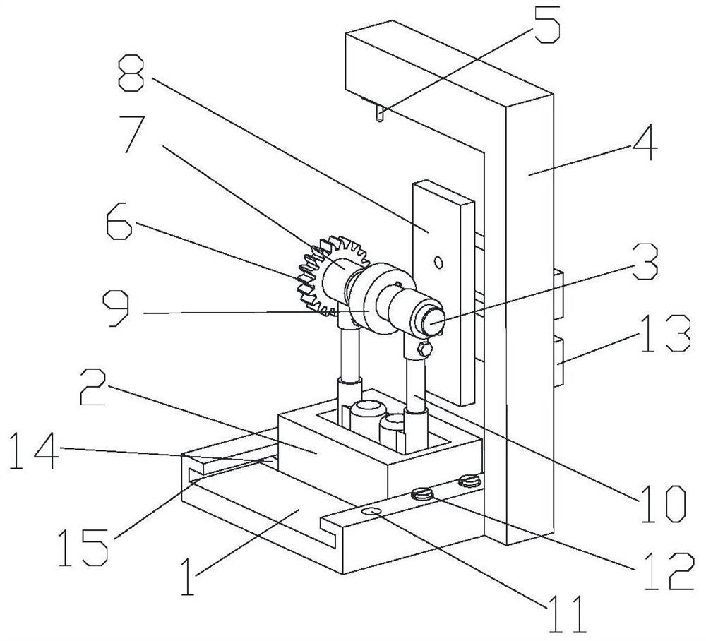
[0004] In order to solve the problem that the conventional laser marking device cannot keep the depth and shape of each processed groove unchanged, the present invention adopts a device for laser processing the surface of an involute cylindrical gear, including a base, a sliding The slide table set on the base, the installation shaft rotatably set on the slide table, the laser marker fixed on one side of the base and the electromagnetic chuck fixed on one side of the base, the The installation shaft is used to install the gear, and a collar is fixed on the installation shaft. The outer diameter of the collar is consistent with the base circle diameter of the gear. The driving mechanism rolling on the electromagnetic chuck, the light emitted by the laser marker is always located on the normal line of the involute of the gear

Method used


Image

  • Device for achieving laser processing on surface of involute cylindrical gear
  • Device for achieving laser processing on surface of involute cylindrical gear
  • Device for achieving laser processing on surface of involute cylindrical gear

Examples


Embodiment 1

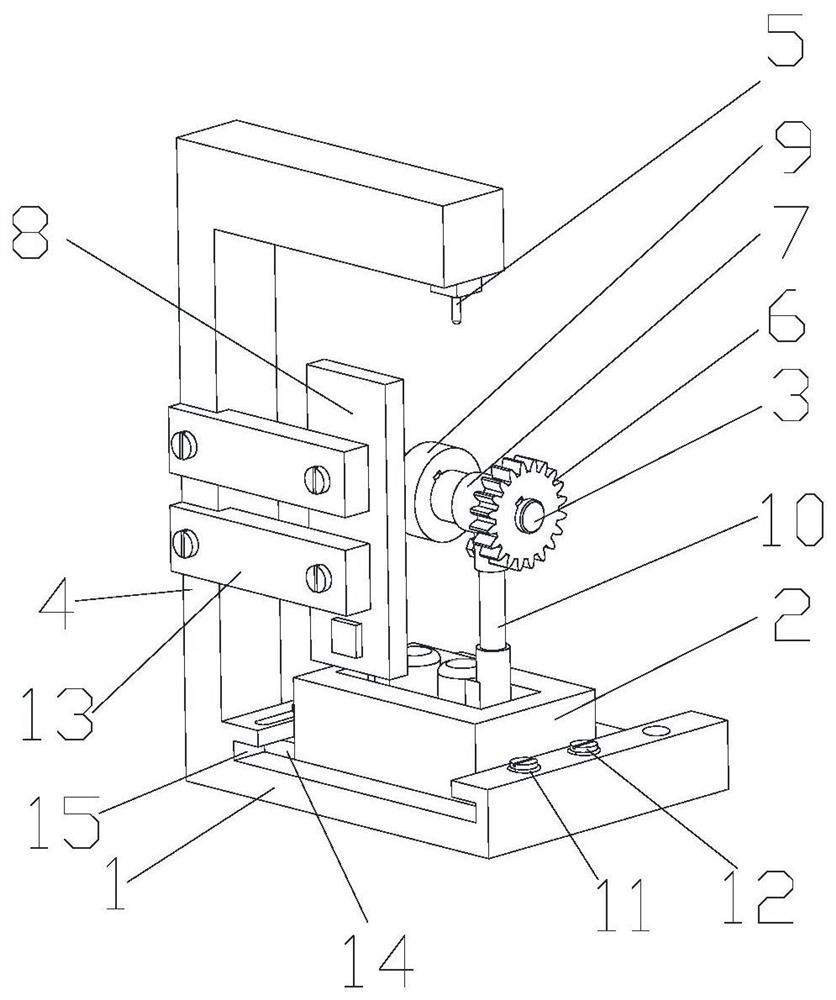
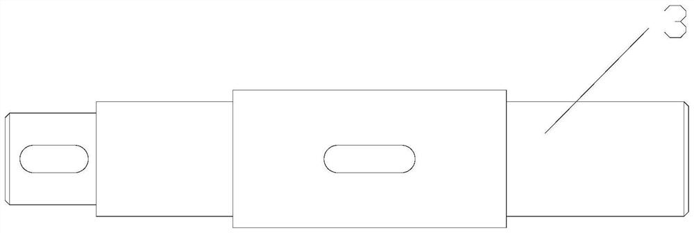
[0020] A device for laser processing the surface of an involute cylindrical gear, comprising a base 1, a slide table 2 slidably arranged on the base 1, an installation shaft 3 rotatably arranged on the slide table 2, and a fixed shaft installed on the base The laser marker 5 on one side of the base 1 and the electromagnetic chuck 8 fixedly arranged on one side of the base 1, the installation shaft 3 is used to install the gear 6, and the electromagnetic chuck 8 in this embodiment is perpendicular to the base 1 Setting as an example for illustration, the installation shaft 3 is fixed with a collar 9, the material of the collar 9 is iron, which is convenient to be absorbed by the electromagnetic chuck 8, and the outer diameter of the collar 9 is consistent with the base circle of the gear 6 The diameters are consistent. In order to prevent the gear 6 from interfering with the electromagnetic chuck 8, the gear 6 is located outside the electromagnetic chuck 8, and the slide table 2...


PUM


Abstract

The invention discloses a device for achieving laser processing on the surface of an involute cylindrical gear. The device comprises a base, a sliding table arranged on the base in a sliding manner, amounting shaft rotationally arranged on the sliding table, a gear fixed to the mounting shaft, a laser marking device fixedly arranged on one side of the base and an electromagnetic chuck fixedly arranged on one side of the base. A lantern ring is fixed to the mounting shaft, and the outer diameter of the lantern ring is basically consistent with the basic circle diameter of the gear. A drive mechanism used for driving the lantern ring to roll on the electromagnetic chuck is further fixed to the sliding table. Light emitted by the laser marking device is located on the normal line of the involute of the gear. According to the device, the lantern ring is controlled by an electric push rod to roll on the electromagnetic chuck, according to the character that the normal line of the basic ring involute of the gear is tangential to the basic ring of the gear, the requirement that a laser beam is perpendicular to the tangent line of the outline of the involute cylindrical gear all the timeis achieved, shapes and depths of machined grooves can keep unchanged, and the precision of the gear face microstructure of the involute cylindrical gear of laser machining is improved.

Description

technical field [0001] The invention relates to the technical field of laser processing, in particular to a device for laser processing the meshing surface of an involute cylindrical gear. Background technique [0002] Friction and wear performance is an important property of the gear surface. Studies have shown that machining microstructures on the gear meshing surface can effectively improve the friction and drag reduction performance of the gear meshing surface. These surface microstructures can not only improve the friction and drag reduction of the gear meshing surface, improve the heat dissipation performance of the gear surface, but also be used to store lubricating oil or debris generated during work. In addition to using methods such as laser shock peening to prepare gear surface micro-textures, laser etching is also a good choice at present. With the development of short-wavelength and short-pulse lasers, laser etching processing technology has become one of the i...

Claims


Application Information

Patent Timeline
Patent Type & Authority Applications(China)
IPC IPC(8): B23K26/362B23K26/70
CPCB23K26/362B23K26/702
Inventor 叶霞朱佳柏范振敏杨澈
Owner JIANGSU UNIV OF TECH
Learn More